Industrial automation and PCB design move fast.Efficiency and reliability matter more than anything.
For decades, screw terminals were the standard.But now applications need faster assembly,especially in tough environments.More engineers and makers are switching to screwless, spring-type terminals.
Why?This guide walks you through wiring with screwless terminal blocks.
1. Faster wiring, lower labor cost
On assembly lines, time is money.Screw terminals need manual tightening.It takes time, and people often over-tighten or under-tighten.
Spring terminals let you just plug wires in.Solid wire or ferrule crimped stranded wire — push it straight in.This cuts wiring time by up to 50%.Lower labor cost is the biggest advantage.
2. Better against vibration
Vibration makes screw connections come loose.That causes breakdowns, repairs, even short circuits.
Spring PCB terminals keep constant pressure on wires.They hold tight in railways, heavy machines, wind turbines.No loosening over time.
3. Spring or screw terminals?
Screw terminals still work great for very high current.But for dense PCBs, vibrating environments, fast assembly —spring terminals are better.
Conclusion
Using screwless terminals in your PCB design improves long-term reliability.
Homnecks is a professional push-in spring terminal block manufacturer. We offer standard and custom solutions.Our engineering team supports your project from start to finish.
Contact us for free samples and technical advice today.
Finding the Right Terminal Block Maker for Your Company
In the electronics business, how good your parts are really impacts how long your product lasts. If you're in charge of buying or designing stuff, picking a good terminal block seller is as important as the circuit design. Here's what to look at when you're checking out who to work with.
Factory or Seller: What’s the difference?
When you're getting parts, you can usually either buy them from someone who sells them from different brands or directly from the company that makes them.
Using a seller: A seller can have different options from different brands and can ship small orders fast. Though if you want a lot of stuff, it might cost you more.
Using a factory: If you buy from the factory, you usually get better prices since you are buying directly. Plus, a factory that only makes terminal blocks will have people who can adjust the product to what you need.
Find a Specialist
Not all factories are the same. If your product is complex, find a maker that is experienced in that area. Makers that know a lot about pluggable tech can make sure everything connects well and lasts a long time.
Why pick us to be your terminal block maker?
We're a top terminal block maker. We're good at giving customers good connections that are certified worldwide. We got it all, from connectors that handle a lot of electricity to small PCB terminals. Because our lines are highly automated, our products are reliable and affordable.
Whether you need a supplier who can reliably ship lots of standard parts or a factory to handle custom designs, we're here to help keep your production going strong.
When you're working on an electronic circuit project, picking the right PCB mount terminal block is super important. It keeps everything safe, reliable, and easy to fix if something goes wrong. There are tons of options out there, so knowing what's what can save you a lot of time and cash. Let's check out some common choices for circuit board designs today.
1. Pluggable PCB Terminal Blocks: Super Handy
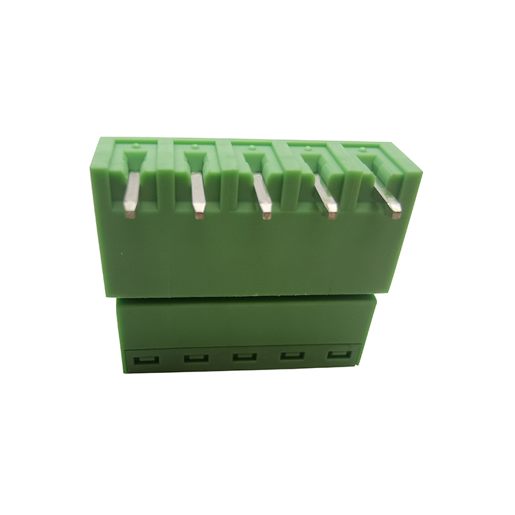
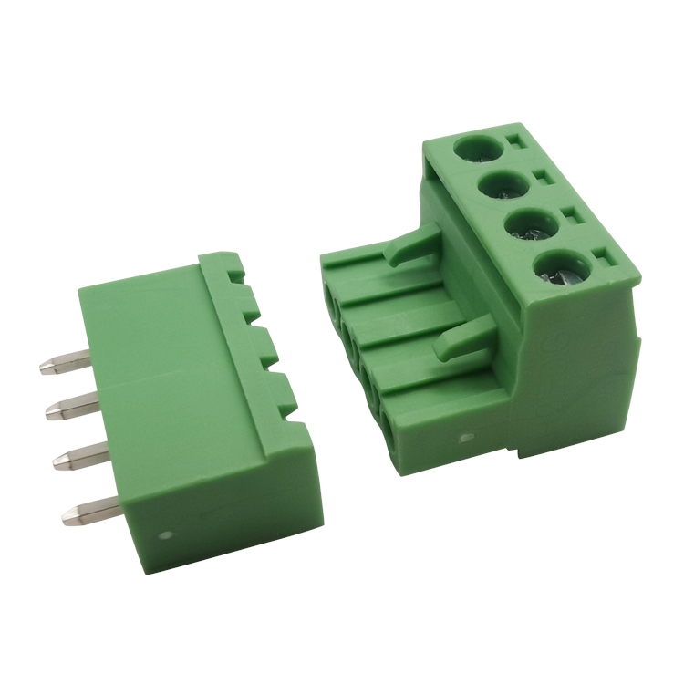
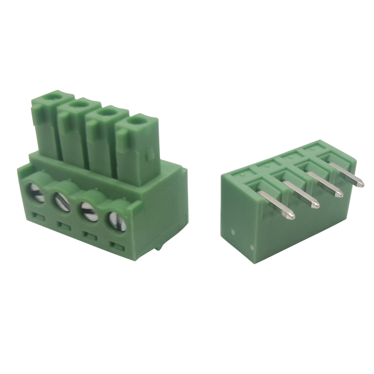
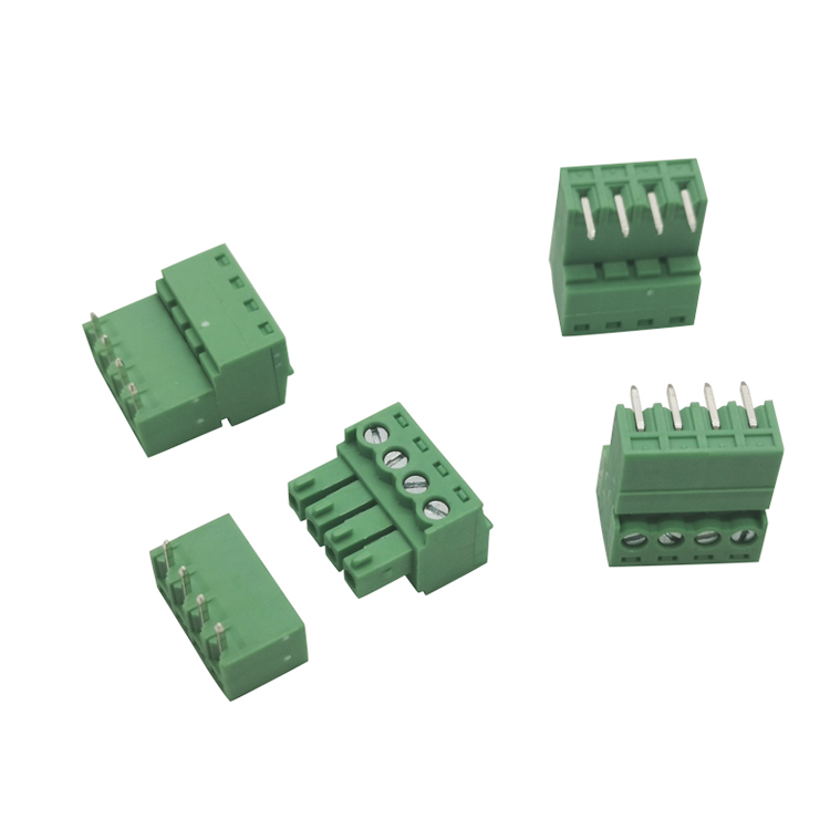
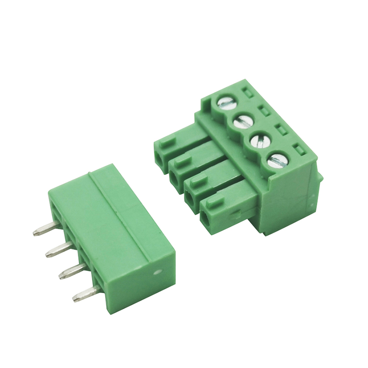
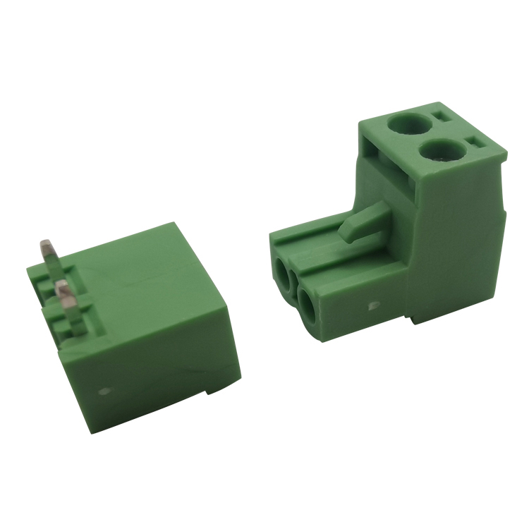
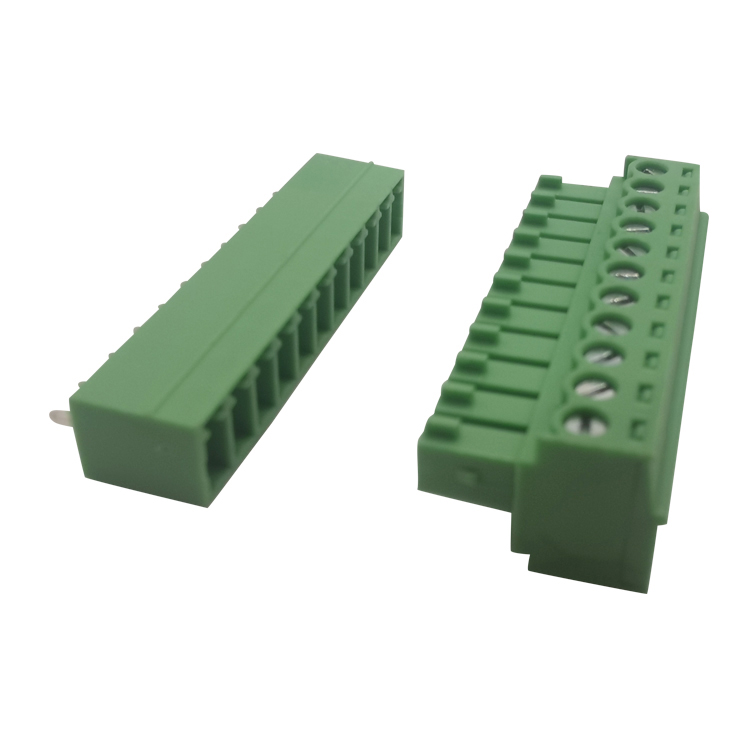
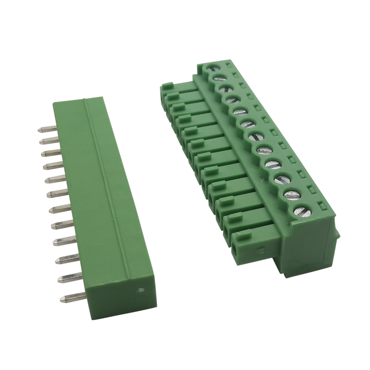
If your system needs regular check-ups, tests, or part swaps, pluggable PCB terminal blocks are the way to go. They have two parts: a socket that you solder onto the board and a plug where you stick the wires.
Easy Fixes: With these, anyone can quickly disconnect a bunch of wires without messing with each one.
Works Everywhere: You can find these blocks in all sorts of things, like air conditioning systems and factory robots.
2. Quick and Safe: Spring vs. Screwless Terminal Blocks
Want to speed up wiring at work? Check out these options.
Screwless terminal blocks mean no screwdrivers needed! Just push a wire into the hole, and you're done.
Spring terminal blocks use a spring to hold the wire tight. They handle bumps well, so the wires stay put even when things get shaky, like in big machines.
3. Old-School but Good: PCB Mount Screw Terminal Blocks
Even with all the new stuff, the regular screw terminal block is still a solid pick. It clamps down super hard and works with many wire sizes. If you're making power supplies or heavy-duty gear that doesn't need to be plugged and unplugged a lot, these are a cheap and strong choice.
So, whether you're thinking about using spring terminal blocks that can handle a beating, or plug-in blocks for a system that’s easy to take apart, getting the right parts is key to a good project. Always get your stuff from reliable people who make sure everything is top-notch.
How to Select Suitable Terminal Blocks for Industrial Projects
Terminal blocks may look like small‑scale components, yet they directly decide the stability of power and signal circuits inside control cabinets, automation lines and power distribution units. Many field engineers have run into avoidable equipment faults simply because they picked mismatched terminal blocks.
This practical guide breaks down 5 core selection factors for industrial terminal blocks: real‑world current load, connection mechanism, working environment, product certifications, plus maintainability and expandability. Use these checkpoints to build safer, more dependable electrical systems for your equipment.
Why Terminal Block Selection Deserves Your Full Attention
Terminal blocks act as critical connection nodes across industrial control panels, distribution enclosures, new‑energy hardware and automated production lines. Poor‑fit terminals bring very real on‑site risks: overheating joints, unexpected voltage drop, distorted signal transmission, and even unplanned system shutdowns.
Design teams often underestimate these compact parts. But bad terminal choices create hidden failure points that show up during long‑term cabinet operation.
1. Calculate Actual Working Current, Not Just Datasheet Rated Value
This is one of the most frequent mistakes we see in cabinet design work.
Manufacturer rated‑current values are tested under ideal lab conditions. Real‑world control cabinets tell a different story. Dense component layout, limited air circulation and high ambient temperature inside the enclosure all push operating temperature higher. These conditions lower the practical current capacity of terminal blocks.
Practical engineering tip: Reserve a 20 %‑30 % current safety margin for your project.
Example: If your continuous working current hits 16A, select terminal blocks rated 20A or above. Never run terminals close to their maximum rated limit for continuous operation.
2. Match Connection Type to Your On‑Site Application
Each connection mechanism carries clear pros and cons. Pick based on your assembly workflow and operating conditions instead of choosing by price only.
Connection Type
Key Strengths
Known Drawbacks
Best Fit Scenarios
Screw‑type Terminal Blocks
High current carrying capacity; solid clamping force for power circuits; wide industry adoption
Screws can loosen under vibration or thermal cycling; periodic re‑torque required
Heavy‑duty power wiring, stationary control cabinets, high‑power distribution systems
Spring / Screwless Terminal Blocks
Constant dynamic clamping force; zero re‑torque maintenance; excellent anti‑vibration performance
Lower max current compared with large screw terminals; stranded wires often need ferrules
Vibration‑prone machinery, rail transit, wind‑power equipment, high‑volume cabinet assembly
PCB Pluggable Terminal Blocks
Fast plug‑and‑play installation; easy module swap‑out; convenient for testing and repair
Mechanical mating wear after repeated plug cycles; needs matching male header
PCB‑based controllers, modular automation hardware, equipment requiring quick disassembly
3. Evaluate Environmental Conditions for Installation Location
Temperature, humidity, dust and chemical vapors inside the cabinet or field site will shorten terminal service life if you ignore them.
For harsh working environments:
- Go for tin‑plated copper alloy pins and conductors. They resist oxidation and corrosion better.
- Confirm housing material meets **UL94 V‑0 flame retardant rating**. PA66 is the common reliable option for industrial terminal block housings.
- For heavy dust or moisture exposure, consider terminal accessories with protective covers or enclosures to reduce contamination risk.
Even indoor control cabinets can reach high internal temperatures under full load. Do not only reference ambient room temperature when selecting components.
4. Verify Required Industry Certifications
Certifications are non‑negotiable for export‑oriented equipment and international projects.
Common mandatory standards include UL, CE, IEC and RoHS. Without these valid certifications, your cabinet or machine may fail third‑party inspection, get held up at customs, or face compliance risks.
As procurement advice: Always ask suppliers to provide corresponding certification documents, rather than trusting product page descriptions alone.
5. Factor in Maintenance and Future Expandability
Many engineers only focus on present circuit demands during component selection, and overlook later‑stage modification and upgrade work.
Think ahead:
- Modular terminal block designs simplify wiring changes when you expand machine functions later.
- Stick to widely standardized pitch sizes (such as 2.54 mm, 3.81 mm, 5.08 mm). Standard specifications make spare‑part sourcing much easier.
- Avoid overly specialized custom terminals unless you have fixed long‑term order volumes. Custom‑only parts create trouble for maintenance replacement.
Good selection balances your current requirements and long‑term total operating cost.
Closing Thoughts
There is no universal “best” terminal block for every industrial project. The right choice always depends on your actual working conditions.
Set aside proper current margins, select connection styles matched to vibration and assembly needs, specify qualified flame‑retardant materials, confirm certification compliance, and leave room for future modification. Following these practical rules helps you cut down on field faults and improve overall reliability for control cabinets and automated equipment.
FAQ
Q1: Why do terminal blocks overheat even when the working current is below the rated value? A: The rated current shown on datasheets is measured under ideal laboratory conditions. Inside sealed control cabinets, crowded wiring and poor heat buildup will lower the actual current capacity. We recommend reserving a 20%–30% current safety margin to prevent overheating risks.
Q2: Which terminal block type works best for equipment with constant vibration? A: Spring / screwless terminal blocks are the top choice. They deliver steady dynamic clamping force and will not loosen over time. Screw-type terminals may gradually lose tension under continuous vibration and thermal cycling.
Q3: Can PCB pluggable terminal blocks be used for long-term industrial operation? A: Yes. Premium pluggable terminal blocks with tin-plated copper pins offer stable electrical performance and good mechanical strength. They are widely used on controllers and modular automation devices where quick disassembly is needed.
Q4: What housing material and flame rating should industrial terminal blocks use for harsh environments? A: PA66 plastic with UL94 V-0 flame retardant rating is the standard pick. Combined with tin-plated copper conductors, it delivers better resistance against high temperature, oxidation and dust.
Q5: Are UL, CE and IEC certifications mandatory for terminal blocks used in export machines? A: For most overseas and international bidding projects, these certifications are required. Non-certified components may fail third-party inspections or cause customs clearance delays. Always request valid certification documents from suppliers before procurement.
Q6: Is it necessary to plan expandability when selecting terminal blocks for new projects? A: Yes. Prioritize standard pitch sizes and modular designs. This makes later circuit upgrades, equipment modification and spare part replacement much easier and cuts long-term maintenance costs.
Terminal block overheating is one of the most frequent hidden faults in electrical control cabinets. It rarely triggers alarms immediately. Instead, it slowly degrades insulation, melts terminal housings, and eventually causes short circuits or unexpected downtime.
From on-site maintenance experience, over 80% of terminal burnout failures are not caused by defective products. They come from improper selection, wrong installation, and neglected daily inspection.
Most panel builders and procurement engineers focus only on current and voltage ratings. They ignore contact resistance, torque standards, and wire matching rules. These small oversights lead to recurring overheating issues in mass-produced equipment.
This blog breaks down the three most common terminal block overheating causes in industrial scenarios. It shares practical field solutions, comparison data, and standardized prevention steps for long-term cabinet reliability.
Why Terminal Block Overheating Matters for Industrial Cabinets
All electrical connections generate minor heat during operation. The danger starts when heat accumulates faster than the terminal can dissipate it.
Continuous overheating ages plastic insulation. It creates carbon traces on terminal surfaces. In humid and dusty workshops, this further leads to arcing, phase-to-phase short circuits, and even cabinet fire risks.
The worst part is intermittency. Loose or mismatched terminals may work fine at low load. They only overheat under peak current or high-temperature working conditions, making troubleshooting extremely difficult.
Top 3 Root Causes of Terminal Block Overheating (Field Verified)
1. Incorrect Installation Torque (Loose or Over-Tightened Connections)
Improper screw torque is the No.1 hidden cause of terminal overheating on production sites.
Many field technicians rely on manual feel instead of torque tools. Under-tightening leaves gaps between wire strands and terminal contact surfaces. It increases contact resistance sharply. According to the I²R heating principle, even a tiny resistance rise generates massive heat under high current.
Over-tightening is equally risky. Excessive torque crushes copper strands and deforms terminal metal sheets. Broken wires cannot bear rated current. Vibration and thermal expansion will further loosen the damaged connection over time.
This creates a vicious cycle: heat accumulation → worse contact resistance → higher temperature → final terminal burnout.
2. Mismatched Wire Gauge and Terminal Current Rating
Mismatched specification is a typical design and procurement mistake.
Some engineering teams use small-gauge wires to save cost. Or they install low-current terminals on high-power motor loops.
When the terminal or wire cannot carry the actual operating current, current density exceeds the design limit. Local overheating occurs continuously. Long-term overload will melt the terminal plastic base and damage adjacent circuits.
Another common error: mixing stranded wires and solid wires without ferrules. Loose stranded wire strands disperse current and create hot spots at contact points.
3. Environmental Pollution and Poor Heat Dissipation
Industrial workshop environments accelerate terminal heat failure easily.
Dust, metal powder, and moisture accumulate on terminal gaps. These contaminants reduce insulation performance and block natural heat dissipation.
In high-humidity seasons, surface creepage occurs between terminals. It produces micro-arcing and continuous heat. For cabinets installed near vibrating equipment or high-temperature machines, poor ventilation worsens heat accumulation and speeds up terminal aging.
Fault Comparison: Overheating Causes & Corresponding Field Symptoms
Engineers can quickly locate problems through visual inspection and temperature detection. This table summarizes typical symptoms and hazards of each overheating cause.
Overheating Cause
Visible Field Symptoms
Potential Hazards
Detection Difficulty
Improper Torque Installation
Local yellow/black burn marks, loose wire shaking, unstable current reading
Intermittent power outage, arcing, wire strand fracture
High (no fault alarm at low load)
Wire/Terminal Spec Mismatch
Overall terminal temperature rise, softened plastic base, overheating under rated load
Insulation aging, permanent terminal burnout, loop short circuit
Medium (obvious under peak load)
Environmental Pollution & Poor Ventilation
Dust accumulation on terminals, damp surface, white oxidation spots
Creepage discharge, phase-to-phase short circuit, cabinet fire risk
Low (easy to find via regular inspection)
Terminal Type Anti-Overheating Performance Comparison
Different terminal structures have distinct heat resistance and anti-loosening capabilities. This table guides BOM selection for high-reliability cabinet design.
Terminal Block Type
Anti-Overheating Performance
Anti-Loosening Ability
Heat Dissipation Condition
Best Application
Standard Screw Terminal
Medium. Relies entirely on manual installation quality
Weak. Prone to loosening under long vibration
Normal. Open structure for basic heat dissipation
Static indoor low-power control circuits
Barrier Terminal
Good. Isolation structure avoids cross-circuit heat conduction
Medium. Barriers limit wire displacement
Good. Independent groove reduces heat stacking
Mains input, high-current power loops
Screwless Push-In Terminal
Excellent. Constant spring tension avoids loose contact heat
Excellent. No screw loosening failure
Medium. Compact structure limits partial heat dissipation
Mass signal wiring, long-term stable operation
Pluggable Terminal
Poor. Plug contact gaps easily generate heat
Weak. Vibration causes poor contact
Poor. Closed plug structure accumulates heat
Low-current modular signal circuits only
Practical Prevention Solutions for Each Overheating Cause
1. Standardize Torque Operation to Eliminate Loose Contact Heat
Abandon manual screwdriver feel judgment. Use professional torque screwdrivers for unified installation.
For conventional industrial terminals, keep torque between 0.5–0.8 N·m for 12–16 AWG wires. Follow manufacturer datasheets strictly for special terminals.
For equipment in vibrating workshops, add regular torque inspection every 3–6 months. Screwless spring terminals are the best upgrade choice to avoid long-term loosening risks.
2. Unify Wire and Terminal Specification Matching
Form fixed BOM matching standards. Never use undersized wires or low-current terminals for high-power loops.
All stranded wires must use crimp ferrules before wiring. This ensures full contact and avoids scattered fine strands causing local overheating.
Reserve 20% current margin during design. It prevents overheating caused by peak current and equipment load upgrade in the future.
3. Optimize Cabinet Environment and Heat Dissipation
Keep cabinet interior clean and dry. Remove dust and metal powder accumulation with dry air blowing during regular maintenance.
Optimize cabinet ventilation layout. Do not install high-current terminals in fully enclosed narrow areas.
For high-temperature and high-humidity workshops, select heat-resistant PA66 terminal blocks with higher temperature grades to improve environmental adaptability.
FAQ: Terminal Block Overheating Troubleshooting & Prevention
Q1: How to quickly judge whether terminal overheating is caused by loose connection or overload?
Check the heating state under no-load and load conditions. If the terminal stays cool at no-load but heats up rapidly with load, it is mostly overload or wire specification mismatch. If the terminal generates intermittent heat and has obvious wire shaking during operation, the root cause is loose torque and poor contact.
Q2: Can overheated terminal blocks continue to work after cooling down?
Not recommended. Once a terminal overheats, its internal metal contact surface and plastic insulation have suffered irreversible aging. It will generate heat more easily under the same current load. Hidden short-circuit and burnout risks remain. Replace the terminal block and re-standardize wiring in time.
Q3: Which terminal type minimizes long-term overheating failure rate for industrial power circuits?
Barrier screw terminals are the most cost-effective choice for high-current power loops. They provide physical isolation to avoid heat cross-interference. With standardized torque installation, they resist vibration and dust pollution effectively. For mass stable signal circuits, screwless push-in terminals eliminate screw loosening fundamentally and reduce overheating failures.
Terminal blocks look like simple, generic components. But they are the weakest link in many electrical control cabinet failures.
Most field issues—intermittent shutdowns, terminal overheating, loose connections, and short circuits—stem from one root cause: wrong terminal block selection.
For panel designers and equipment procurement engineers, picking terminals based only on price or basic size leads to costly after-sales repairs. Every project has unique circuit loads, installation environments, and production demands.
After years of on-site cabinet assembly and troubleshooting, we summarize5 non-negotiable key factors for terminal block selection. This guide delivers practical, field-verified rules to help you match the best terminals for your project and avoid common engineering mistakes.
1. Electrical Rating Matching (Current & Voltage Safety Margin)
Electrical rating is the foundation of terminal block selection. It is also the most frequently underestimated parameter in project design.
Many engineers select terminals strictly according to the circuit’s rated current. This leaves zero margin for peak load, temperature rise, and current fluctuation.
From field experience, long-term operation will degrade terminal conductivity. Running terminals at full rated current inevitably causes overheating and aging.
Practical engineering rule: Reserve at least 150% current safety margin. The terminal’s voltage rating must also exceed the system’s maximum voltage, including transient surge voltage.
For industrial high-humidity and dusty workshops, prioritize terminals with larger creepage and clearance distances. They prevent arcing and surface discharge under harsh working conditions.
2. Wire Gauge Compatibility & Connection Stability
Mismatched wire gauge and terminal clamp range is a top hidden fault in mass production projects.
A terminal that is too large cannot clamp thin stranded wires tightly. Loose wire strands create high contact resistance and trigger overheating. A terminal that is too small will crush thick wires, damaging conductors and reducing current carrying capacity.
Another common on-site mistake: using stranded wires without ferrules. Scattered fine strands easily cause phase-to-phase short circuits under vibration.
Always confirm the terminal’s applicable wire range (AWG or mm²). Match solid wire, stranded wire, and flexible wire types to avoid connection failure risks.
3. Terminal Connection Type (Match Production & Maintenance Needs)
Screw, barrier, screwless push-in, and pluggable terminals each fit different project scenarios. No single type works for all circuits.
The table below compares four mainstream terminal types, helping you select based on production volume, on-site vibration, and maintenance frequency.
Terminal Type
Core Field Advantages
Key Limitations
Best Project Application
Standard Screw Terminal
Low cost, full wire compatibility, easy on-site repair, wide stock availability
Prone to vibration loosening, inconsistent manual torque, slow bulk wiring
Low-budget custom projects, static indoor low-power circuits
Barrier Terminal
Independent isolation barrier, anti-short circuit, excellent vibration resistance, low overheating risk
Slightly larger footprint, moderate material cost
Mains input, high-current power loops, vibration-prone workshop cabinets
Screwless Push-In Terminal
Tool-free fast wiring, constant spring tension, no screw loosening, high production efficiency
Higher unit price, poor adaptability for ultra-thick high-current cables
Mass standardized cabinet production, large-scale signal wiring
Pluggable Terminal
Pre-wiring support, fast module replacement, zero on-site rewiring
Weak vibration resistance, high intermittent contact risk
Modular equipment, frequently disassembled control modules
4. Environmental & Mechanical Adaptability
Indoor static office cabinets and factory workshop cabinets require completely different terminal specifications.
Industrial environments have three core interference factors: vibration, dust, and humidity. Ordinary terminals age rapidly in harsh conditions.
Cabinets installed on motors, conveyors, and production lines must prioritize anti-vibration terminal structures to avoid loose connections.
For dusty and humid workshops, select terminals with high-grade insulating plastic (PA66 flame retardant). They resist oxidation, creepage, and long-term environmental erosion.
5. Certification & Project Cost-Benefit Balance
Certification compliance determines equipment market eligibility and safety baseline.
Export equipment requires UL, IEC, or CSA certified terminals. Domestic industrial projects need compliant VDE and flame-retardant certifications to pass factory safety audits.
For cost control, avoid two extremes. Do not over-specify all terminals to raise project costs. Do not blindly choose low-price uncertified terminals to save costs, which leads to frequent failures.
Best cost-performance strategy: Deploy high-safety barrier terminals for core power circuits, and economical standard terminals for ordinary signal circuits.
Quick Selection Parameter Cheat Sheet
This table sorts core selection thresholds for quick BOM review and specification confirmation, suitable for daily engineer and procurement work.
Selection Parameter
Industrial Standard Requirement
Field Best Practice
Current Margin
100% rated current matching
Reserve 150% load margin to avoid thermal aging
Voltage Margin
Equal to system voltage
25% higher than max system surge voltage
Wire Matching
General wire range adaptation
Strictly match wire type + AWG, use ferrules for stranded wires
Vibration Environment
No special requirement
Choose barrier or screwless terminals for vibrating equipment
Certification
Basic safety certification
Match local market access standards (UL/IEC/CSA)
FAQ for Terminal Block Project Selection
Q1: Is it necessary to reserve current margin when selecting terminal blocks?
Yes, it is mandatory for industrial projects. Operating terminals at full rated current will cause continuous heat accumulation with load fluctuation and temperature changes. Reserving 150% current margin effectively prevents thermal aging, overheating, and loose connections. It is the most cost-effective way to reduce long-term failure rates.
Q2: Which terminal type is the most versatile for most control cabinet projects?
Mixed configuration is the most practical solution. Use barrier terminal blocks for mains input and high-current power circuits to guarantee safety and vibration resistance. Adopt screwless push-in terminals for mass signal wiring to improve assembly efficiency. Deploy standard screw terminals for low-budget auxiliary circuits to control overall project costs.
Q3: Do terminal certifications really matter for non-export domestic projects?
Absolutely. Certified terminals have standardized insulation, flame retardant, and creepage distance parameters. Uncertified low-cost terminals often cut material corners. They are prone to insulation breakdown and arcing in harsh industrial environments, leading to safety hazards and failing customer factory safety audits.
If you're an engineer, buyer, or seller, it's important to know about the different kinds of terminal blocks, Pitch, and where they're used.
I. Regular PCB Terminal Types
1. PCB Screw Terminals
These are strong and conduct electricity well, so they're good when you need a really reliable connection.
You'll often see them as 2-pin or 3-pole setups.
2. Pluggable PCB Terminals
These are made to be plugged in and out quickly, which makes fixing or switching things out easier.
They're common in industrial control boxes and automation systems.
3. Spring Terminals / Screwless Terminals
These are fast to install and don't shake loose easily, which is good for PCBs with a lot of wires packed close together.
II. What You Need to Know About PCB Terminal Spacing (Pitch)
The spacing between pins depends on how much current and voltage you need:
- 3.5mm / 3.81mm: For signals and when you don't need much current
- 5.0mm / 5.08mm: For industrial controls and power units
- 7.5mm / 7.62mm: For high current and voltage
III. Where Barrier Terminal Blocks Are Used
Barrier terminal blocks have more space between the connections and are safer.
They're usually found in power equipment, industrial control systems, and PCBs that handle a lot of power.
IV. Why Go with a Terminal Maker?
Buying straight from a terminal maker, factory, or provider means you get:
- Products that are always good quality
- The option to get things made the way you want
- Better prices
- Delivery you can count on, which is good for big orders
In conclusion:
From screw terminals to pluggable and insulated ones, picking the right terminal and spacing is key for a safe and well-performing system.
As a terminal factory, we give customers everywhere good terminal solutions.
In industrial control, power systems, automation equipment, and electronic products, terminal blocks are one of the most common and critical connectors.Choosing the right type of terminal block (such as pluggable PCB terminals, screw terminals, or spring terminals) not only affects wiring efficiency but also directly impacts system stability and future maintenance costs.
I. What are Pluggable PCB Terminal Blocks?
Pluggable PCB terminal blocks consist of two parts: a plug and a base, allowing for quick insertion and removal without the need for rewiring.
This type of terminal block is widely used in modular equipment and industrial control systems.
Advantages include:
- Fast installation and maintenance
- Reliable connection and stable contact
- Suitable for PCB mounting
- Available in various pitch sizes, such as 3.5mm, 3.81mm, 5.0mm, 5.08mm, 7.5mm, and 7.62mm
II. Screw Terminal Blocks: Characteristics
Screw terminal blocks secure wires using screws, resulting in a robust structure. They are one of the most common types of terminals in industrial applications.
Main Features:
- Secure wire fixation with strong tensile strength
- Suitable for medium to high current applications
- Low cost and high versatility
- Available in various configurations, including PCB mount screw terminals, 2-pin, 3-pole, etc.
III. Spring/Screwless Terminal Blocks
Spring terminal blocks use spring clips to secure wires, eliminating the need for screws and improving assembly efficiency.
Key Advantages:
- Fast wiring, reducing labor time
- Excellent vibration resistance
- Suitable for high-density PCB designs
IV. PCB Mounting Terminals and Barrier Terminal Blocks
In applications requiring high insulation distance and safety, barrier terminal blocks are widely used,
suitable for power supplies, power control, and industrial equipment.
V. How to Choose the Right Terminal Block?
When selecting a terminal block, it is recommended to focus on:
1. Terminal spacing (Pitch)
2. Current and voltage ratings
3. Wiring method (screw/spring/pluggable)
4. PCB mounting method
5. Frequency of future maintenance
Conclusion:
Whether it's pluggable terminals, PCB-mounted terminals, or spring terminals, choosing the right terminal solution can significantly improve system stability.
As a professional terminal manufacturer and supplier, we can provide customized PCB terminal solutions for our customers.
The torque of terminal blocks (specifically screw-type terminals) is the most critical and direct installation parameter affecting their connection reliability. It is not an isolated value, but a key control point in a precision engineering system. The following explains the relationship between the two, from principle to practice.
Core Principle: How is torque converted into a reliable electrical connection?
The physical chain of events can be simplified as follows:
Applied torque → Generation of clamping force (axial force) → Formation of contact pressure → Determination of contact resistance → Impact on long-term reliability
Torque (T): The rotational force applied during installation using a screwdriver or wrench, typically measured in Newton-meters (N·m) or centiNewton-meters (cN·m).
Clamping force (F): The axial compressive force generated between the wire, terminal block, and conductive strip as the screw is rotated and tightened. This is the core purpose of the torque.
The relationship is influenced by several factors: F ≈ k * T / d (where k is the overall friction coefficient, and d is the nominal diameter of the screw). The friction coefficient is a key variable and is greatly affected by the threads, washers, and surface condition of the wire.
Contact pressure (P): The actual pressure generated by the clamping force at the microscopic contact points. Sufficient contact pressure can:
Break through the oxide film: The surface of the conductor (usually aluminum or copper) has an insulating oxide film; high pressure can break this film, creating metal-to-metal contact.
Increase the contact area: Cause controlled plastic deformation of the conductor, increasing the effective conductive area.
Maintain stable contact: Resist loosening caused by vibration and thermal expansion and contraction.
Contact resistance (Rc): Contact pressure directly determines the magnitude of contact resistance. There is a critical pressure above which the contact resistance tends to stabilize at a very low value; below this value, the resistance increases sharply.
Low and stable Rc means: low power loss (P_loss = I² * Rc), low heat generation, high current carrying capacity, and good signal integrity.
The torque applied to terminal blocks is not simply a matter of "tightening," but rather a precise engineering control parameter. It is the bridge that transforms mechanical energy into a stable electrical connection.
Reliability formula: Reliable connection = Correct torque × Suitable wire × Standardized process × Matching terminal design.
Core understanding: The "correctness" of the torque directly determines the "stability" of the contact resistance, which in turn is crucial for long-term electrical reliability.
Ignoring torque control is equivalent to planting a time bomb in the connection point, a fault that will inevitably trigger over time.
Therefore, in any serious industrial, energy, or transportation sector, incorporating and strictly controlling wiring torque in process specifications is an essential measure to ensure the reliability of fundamental system connections.
Terminal blocks are one of the most basic and crucial components in electrical connections, with the core objective of achieving safe, reliable, and convenient wire connections.
I. Operating Principle
The basic principle of a 8 pole terminal block can be summarized as follows: through a mechanical structure and a conductor, it establishes a low-resistance, high-stability electrical path between conductors (such as wires), while ensuring a firm mechanical connection and preventing accidental contact.
This principle primarily relies on the following key points:
Electrical conduction: The core conductor of the terminal (usually copper or copper alloy) provides the main path for current flow. Its excellent conductivity ensures low energy consumption and low heat generation.
Mechanical clamping: Through screws, springs, or other mechanical devices, a substantial contact pressure (clamping force) is exerted on the inserted wire. This force serves two important purposes:
Destruction of oxide layer: The oxide film on the surface of the wire is non-conductive. A strong clamping force can crush this thin film, enabling true contact between metals.
Maintain contact: Prevent wire loosening caused by vibration, thermal expansion and contraction, or external force pulling, and maintain stable contact resistance.
Minimizing Contact Resistance: Ideally, the flow of current from a wire to a terminal and then to the next conductor should be as smooth as possible. Good design and clamping force can ensure that the resistance at the contact point is much lower than the resistance of the wire itself, thus preventing the point from becoming a "hot spot".
II. Design Structure
Despite the diverse shapes of wiring terminals, most of them consist of three basic components:
1. Conductive material: Typically, metals with high conductivity are used, such as brass, phosphor bronze, and copper alloys. Sometimes, they are plated with tin, nickel, or silver to enhance corrosion resistance, reduce contact resistance, and improve solderability.
Function: This is the core channel for current transmission. It is designed to connect reliably with wires and form an electrical interface with matching terminals or devices.
2. Insulating shell material for 8 position terminal block : Engineering plastics, such as polyamide (PA66, nylon), polycarbonate (PC), PET, etc., are commonly used. These materials exhibit good electrical insulation, mechanical strength, flame retardancy (such as UL94 V-0 grade), and heat resistance.
3. Clamping mechanism is the key part to distinguish different types of terminals. There are mainly the following mainstream designs:
a) Screw connection type
Structure: By rotating the screw, a metal pressure plate or conical nut is driven to directly compress the wire.
Advantages:
The connection is firm, with a large contact area and strong current-carrying capacity.
Suitable for connecting single-strand (solid) wires and multi-strand wires with wire lugs.
Disadvantages:
It may loosen in a vibrating environment, so regular inspection and tightening are required.
The connection speed is relatively slow.
For multiple thin wires, if a wire nose is not used, some copper wires may be crushed and broken during tightening.
b) Spring connection type (cage spring/compression spring type)
Structure: Utilize a pre-tensioned V-shaped or other shaped spring leaf. Insert a straight screwdriver into the operating hole to open the spring. After inserting the wire, withdraw the screwdriver, and the spring will rebound, firmly pressing the wire against the internal conductive strip.
Advantages:
Vibration resistance: The continuous pressure of the spring can compensate for the looseness caused by thermal expansion and contraction and vibration, making it very reliable.
Quick wiring: No need to twist screws, greatly improving wiring efficiency.
Suitable for multi-strand wires and thin wires with casings.
Disadvantages:
Strong dependence on tools (requires a screwdriver of a specific size).
The current-carrying capacity is generally slightly lower than that of screw connections of the same size (but it is sufficient in most cases).
c) Direct plug-in connection
Structure: This is a simplified form of spring connection. It usually has a small hole, into which a stripped and untreated solid wire is directly inserted with force. The internal spring mechanism will automatically clamp the wire. To release the wire, you need to press the release button next to it.
Advantages:
It is extremely fast and convenient, and the terminal block 10 pin can be made without any tools.
Disadvantages:
It is usually only applicable to solid conductors.
The current-carrying capacity and wire diameter range are limited.
d) Insulation displacement connection
Structure: Inside the terminal, there are sharp V-shaped metal contacts. When a unstripped wire is pressed firmly into the designated position, the sharp contacts pierce through the insulation and make direct contact with the internal metal conductor.
Advantages:
No need to strip the wire, saving time and effort, and avoiding problems caused by improper wire stripping length.
The connection is fast and reliable.
Disadvantages:
There are strict requirements for the specifications of the wires and the thickness of the insulation.
It is commonly used in signal current applications such as communication, data networks (such as RJ45 connectors), and home appliances.
III. Main Types and Applications
According to application scenarios, terminal blocks mainly come in the following forms:
PCB terminal block: soldered onto a printed circuit board, used to connect external wires to the circuit board.
DIN-rail terminal blocks: They can be clipped onto standard DIN rails and are widely used in industrial control cabinets and distribution boards, facilitating modular installation and maintenance.
Barrier terminal block: 12 position terminal block Equipped with plastic partitions, it is commonly used in high-voltage and high-current applications such as power distribution, effectively preventing short circuits between different polarities.
Socket terminal: used for connecting devices that require frequent plugging and unplugging.
IV. Design Considerations and Selection Key Points When designing or selecting terminal blocks, the following factors must be considered:
Current and voltage ratings: These are the most crucial parameters, which must meet or even exceed the maximum demand of the circuit, while leaving a margin.
Wire type and specification: Is it a single-strand wire or a multi-strand wire? What is the wire diameter (AWG or square millimeter)? This determines which clamping mechanism should be selected.
Environmental conditions: Is it exposed to high vibration, high temperature, high humidity, or corrosive environments? This affects the selection of materials (such as housing plastics, plating layers) and connection methods (such as spring connections for better vibration resistance).
Safety certification: Whether it is necessary to comply with safety standards in specific regions, such as UL (United States), UL (Canada), CE (Europe), VDE (Germany), etc.
Number of wires and spacing: How many wires need to be connected? Does the spacing (pitch) between terminals meet the requirements for electrical clearance and creepage distance?
Summary
Although terminal blocks are small components, they are the "joints" of the electrical system. Their working principle is based on reliable mechanical clamping to achieve low-resistance electrical contact. Their design structure revolves around three major elements: conductors, insulating shells, and clamping mechanisms. For different application needs, various clamping technologies such as screws, springs, direct insertion, and insulation displacement have been derived. Proper selection and installation are the foundation for ensuring long-term stability and safe operation of the entire electrical system.
This is a highly practical and crucial issue. Selecting the right terminal block for equipment is key to ensuring safe, reliable, and long-lasting electrical connections.
This a clear and systematic selection guide, which you can follow to find the most suitable terminal for your equipment.
Step 1: Clarify Requirements — Understand What You Need
1.Current load (amperes, A)
This is the most important parameter. The terminal must be able to safely carry the maximum continuous current in the circuit and leave appropriate margin (usually it is recommended to choose a terminal with a rated current 20-30% higher than the actual maximum current).
The consequences of incorrect selection: Overloading can cause terminals to heat up, melt, and even trigger fires.
2.Voltage level (volts, V)
The terminal needs to be able to withstand the operating voltage and possible transient overvoltage in the circuit.
Common voltages include low voltage (such as 12/24/48VDC), industrial control voltage (110/220VAC), or higher voltage.
3.Wire specifications (wire diameter, mm ² or AWG)
The terminal must perfectly match the cross-sectional area of the wire. Too much pine can cause poor contact and overheating; If it is too tight, it will damage the wire.
Please accurately measure the square of the wire (mm ²) or the American Wire Gauge (AWG) value.
4.How many wires need to be connected?
Single core wire vs multi stranded wire: Some terminals (such as pin crimping terminals) are only suitable for multi stranded wires, while wiring blocks can accommodate both, but it is sometimes recommended to use pin terminals for multi stranded wires.
Number of wires: Is it a 1-to-1 connection, a 1-to-many connection, or is it necessary to connect multiple wires to one point?
5.How is the usage environment?
Temperature: Is the ambient temperature very high (such as near the engine) or very low?
Humidity: Is it used in a damp or humid environment?
Vibration: Is the equipment in a vibrating state (such as vehicles, machine tools)? Terminals with anti vibration design are required for vibration environments.
Chemical substances: Will they come into contact with oils, solvents, or other chemicals?
Outdoor use: Do you need UV protection, waterproof and dustproof (refer to IP rating)?
Step 2: Key Selection Parameter Checklist
Match the requirements of the first step with the specifications of the terminals:
Parameters
Parameters
Terminal specification sheet
Electrical
Current (A)/Voltage (V) Rated
Current/Voltage
Mechanical
wire specification (mm ²/AWG)
applicable wire range
Screw torque (if any)
Recommended torque (N · m)
Connection type (screw, spring, plug)
wiring technology
Environmental
temperature
operating temperature range
Protection level IP
rating (such as IP20, IP67)
Certification requirements (export)
UL, cUL, VDE, T Ü V, etc
Material
Corrosion resistant and conductive conductor material
usually copper, with tin/nickel/silver plating on the surface
Insulation and flame retardant
insulation material (usually PA66 nylon, with UL94 V-0 flame retardant rating)
Step 3: Practical suggestions and summary
Quality priority: Do not use inferior terminals of unknown origin. They may use inferior materials (such as iron instead of copper), thin coatings, and non flame retardant insulation materials, which are serious safety hazards.
Matching tool: For crimping terminals, it is strongly recommended to use professional crimping pliers. Using mismatched tools or pliers for crimping cannot guarantee the quality of crimping, which can easily lead to poor contact.
Sample testing: Before bulk procurement, if conditions permit, a small amount of samples can be purchased for testing. Check its clamping force, conductivity, and temperature resistance.
Seeking professional help: If unsure, you can ask us for help ,NingBo HongYi Electronic Co., we will give you a professinal answer.
To summarize, the process of finding the correct wiring terminals for a device is:
Clear requirements (current/voltage/wire diameter/environment) → Verify parameters (rated value/material/certification) → Practical verification (tools/samples)
By following this process, you can find the safe and reliable "right terminal block" for your device.
This is an excellent question that directly addresses the core of electrical system reliability. Why terminal block quality so important?because its the key for integrity, stability, and safety of the "conductive circuit." We can delve into this matter from several dimensions: materials, design, manufacturing process, and practical implications.
1. Materials: The Physical Basis of Conductivity
Conductivity is primarily determined by the material. High-quality terminal blocks are made from materials with excellent conductivity and undergo necessary surface treatments.
Main material (conductive sheet):
Premium Options: High-purity oxygen-free copper (e.g., TU1) or copper alloys (e.g., brass, phosphor bronze). These materials exhibit low resistivity and excellent conductivity, while phosphor bronze also offers superior elasticity and fatigue resistance, ensuring long-term contact pressure maintenance.
Low-quality materials: Using recycled copper with high impurities, copper-clad aluminum, or even iron coated with copper. These materials exhibit high electrical resistance, severe heat generation, and are prone to corrosion, posing significant safety hazards.
Plating layer: Key corrosion-resistant and contact-enhancing layer.
Tinning: The most common method, with moderate cost, effectively prevents copper substrate oxidation while maintaining excellent solderability and contact.
Silver plating: Offers the best conductivity and strong oxidation resistance, commonly used in applications requiring extremely low contact resistance or high-frequency signals (though silver can sulfidize in sulfide environments).
Nickel/Plated Gold: Excellent wear and corrosion resistance, suitable for high reliability, frequent plugging and unplugging, or harsh environments.
Low-quality products: thin and uneven coatings with poor adhesion, which wear or oxidize quickly, leading to a sharp increase in contact resistance.
2. Design and Craftsmanship: Transforming Material Properties into Reliable Connections
Good materials require good design and craftsmanship to achieve.
Contact Design:
Pressure and Area: The spring or screw structure must provide sufficient, stable, and uniform contact pressure. Insufficient pressure results in high contact resistance, while excessive pressure may cause plastic deformation of the cable or spring, leading to failure.
Contact point protection: The design should minimize the erosion of contact points by environmental factors (dust, moisture, corrosive gases).
Structural Strength and Insulating Materials:
Insulated housing: Must be made of flame-retardant, high-temperature-resistant, and high-CTI (Comparative Tracking Index) engineering plastic (e.g., PA66+GF). Inferior plastics are prone to aging, deformation, or even combustion, which can cause short circuits or fires.
Mechanical strength: Structures such as clips, guide rail grooves, and screw mounting seats must be robust and capable of withstanding stresses from installation, operation, and vibration.
Process consistency:
Precision Machining: Ensure consistent dimensions and tight tolerances at every contact point.
Reliable fasteners: The strength of screws, thread accuracy, and anti-loosening designs (such as screws with saddle washers) are crucial.
Conclusion: Terminal blocks are the "gatekeepers" of system safety
In modern electrical and control systems, although terminal blocks are inconspicuous passive components, they undertake multiple key functions such as current transmission, signal connection, circuit isolation, and physical fixation.
High quality terminal block: Like a loyal "goalkeeper", it ensures low loss, zero distortion, and high reliability of electrical energy and signals, resists environmental erosion and mechanical stress throughout the entire life cycle of the equipment, and is the cornerstone of safe, stable, and efficient system operation.
Low quality terminal block: It is a hidden time bomb in the system. The small cost savings it saves are completely insignificant compared to the potential costs of equipment damage, production downtime, data loss, and even personal safety accidents.
Therefore, when choosing a terminal block, it must not be regarded as a simple "wiring tool". The strict requirements for its materials (conductivity and coating), design (contact and insulation), and process (consistency) are the basic guarantees for the investment and personal safety of the entire electrical system. Always adhere to selecting products that comply with international standards (such as UL, IEC, VDE) and come from reliable manufacturers, which is the wisest choice.
 English
 English
 Deutsch
 Español
 عربي
عربي हिंदी
हिंदी

 Contact Us



 IPv6 network supported