Whether it’s EV charging stations for new energy vehicles,or large power cabinets in regular factories,safe electrical connection always comes first.
Loose wiring is a huge hidden risk.It causes random shutdowns.It leads to local overheating.In the worst cases, it even sparks fire hazards.
Below we break down how to pick the right terminal blocksfor different working conditions.
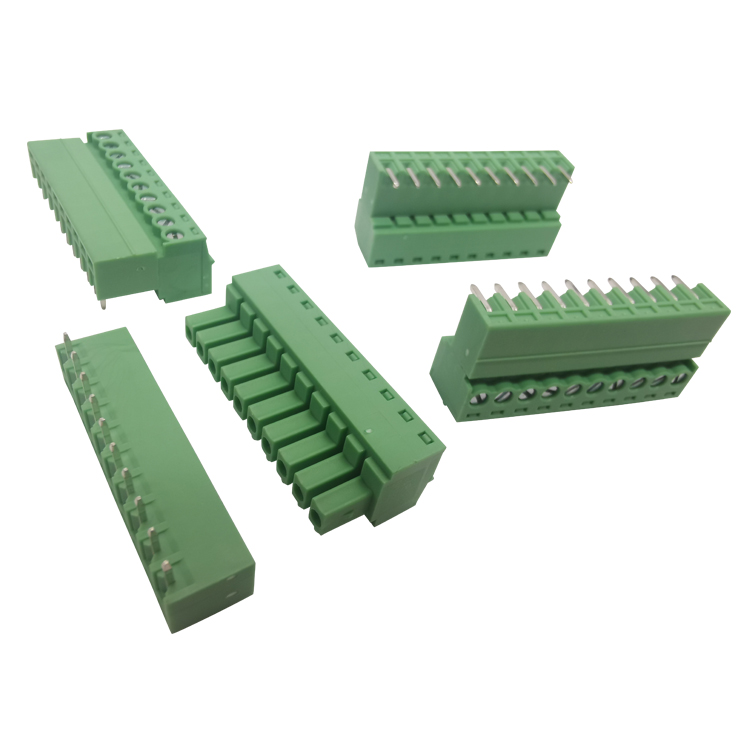
1. Ideal choice for high power and high voltage use
Heavy-duty power cabinets often run with thick wiresand sudden high current surges.In these scenarios, barrier screw terminal blocksstill stay as the most reliable option.
It features raised insulated baffles on every pole.This simple structure stops messy wires and stray debrisfrom causing short circuits.
For three-phase main power input,engineers widely use standard 3 pole terminal blocks.Strong screw clamping force holds wires firmly in place.It keeps high current stable,and greatly cuts down overheating risks.
2. Vibration resistance and tool-free wiring, the new mainstream
Many devices work under continuous strong vibration.Wind power units, heavy industrial machinery, you name it.Standard screw terminals will slowly loosen over time,purely from constant shaking.
This is why spring terminal blocks are getting more popular.Built-in high-toughness springs deliver steady, lasting pressure.Wires stay locked tight all the time, no loosening at all.
This screwless design saves plenty of on-site work.Workers don’t need to keep checking and tightening screws.No routine re-tightening work later on.It speeds up field installation and daily maintenance a lot.
3. Smart purchasing tips and reasonable cost control
If you manage procurement for smart buildingsor large-scale lighting projects,bulk sourcing cost-effective low-voltage terminal blocksis an easy way to keep your budget under control.
Unstable product quality always brings extra rework cost.It’s smarter to team up with a qualified terminal block wholesaler.Look for suppliers with full product lines and complete certifications.
Long-term cooperation lets you finish one-stop purchasing.It also meets the complicated power distribution needsof modern building systems.
Industrial automation. Smart control board design.
What’s most important?
Fast installation. Easy maintenance later.
That’s the core need.
Old connection methods? They’re on their way out.Engineers? They want easy, time-saving electronic connections.No more hassle.
This guide? It tells you briefly.How to pick the right parts for your industrial design project.Simple, no fancy stuff.
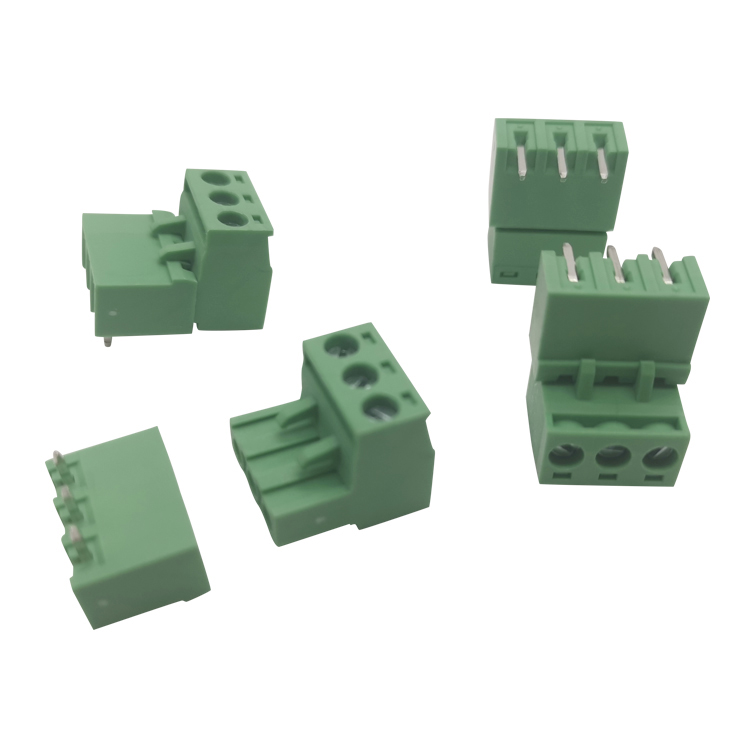
1. Ditch the hassle, go for plug-in design
Back in the day, lots of old equipment used PCB screw connectors.Yeah, they’re cheap.But fixing them later? Such a pain. So time-consuming.
Electricians on site? They have to take out every wire one by one.In tiny spaces. So frustrating.
Now? Plug-in terminal blocks fix this problem.Plug and play. Done.
They save so much time on the production line.When equipment breaks? Swap it in seconds. Hot swap too.Maintenance costs drop a lot. A whole lot.
2. How to pick the key specs?
Designing a circuit board?Matching the physical specs right is super important.No mistakes here.
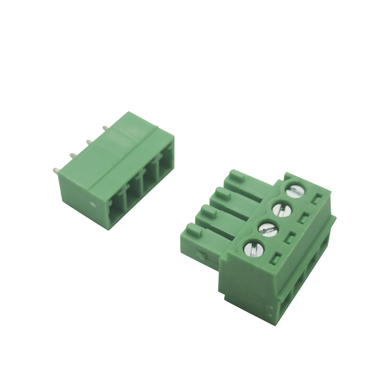
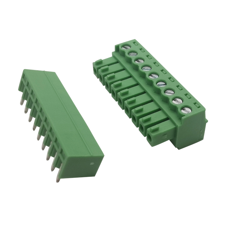
First, pick the pitch.A standard PCB mount terminal block factory?The pin pitch decides two things.Max voltage it can handle. And how much panel space it takes.
Industrial control? 5.08 mm terminal blocks are still the best.Why? Good electrical safety clearance. Great creepage performance.They’re the gold standard for automation equipment right now.Everyone uses them.
Then, the number of poles.Three-phase power control? Signal transmission with separate grounding?Terminal block 4 pin is the most common.Buys the most often.Fits most regular wiring logic. Neat and perfect.
3. Tips for efficient supply chain purchasing
Global market is tough. Competitive.Batch stability of products? It decides the final quality.
To make sure your equipment meets international safety certifications?More buyers skip middlemen.They go straight to pluggable terminal block manufacturers.The ones with their own testing labs.Buy in bulk directly.
Working with the source factory?No more late deliveries. Stable lead times.And you can make sure the plastic housing has good flame retardant rating.Metal contacts last long, too. Conduct well, no issues.
Time is everything in modern industrial automation.When equipment goes down — whether it’s a motor control center, PLC module, or power panel —it costs real money.
That’s why industrial pluggable terminal blocks have become the top choice for engineers.They’ve completely changed how machines get installed and maintained.This article shows why your next automation project should use pluggable design.
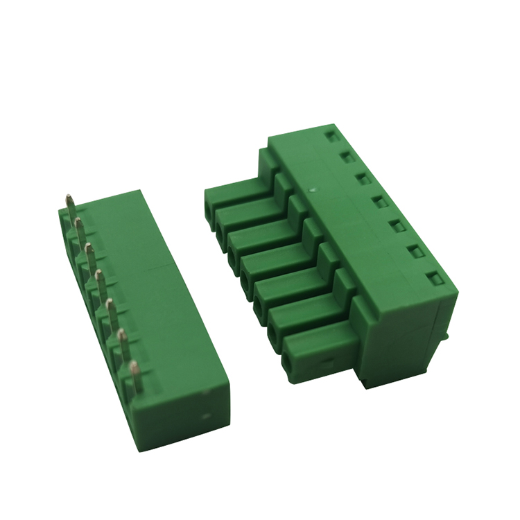
1. Real modular design. Plug and play, simple.
With old wiring, replacing a broken module means removing every wire one by one.It takes time.And people often wire things wrong.
But with good plug-in terminal block connectors,you can pull out a whole control board or sensor in seconds and swap it.This works really well in spring terminal block applications.Faster assembly.Easier on-site maintenance.
2. Handle high loads and motor control
Industrial sites use high voltage and high current.Regular terminals can overheat or even fail under constant heavy use.
That’s why a dedicated pluggable terminal block for motor control is so important.They use high-purity conductive materials and strong housings.Perfect for servo motors and inverters.
For industrial boards that need extra strength,heavy duty PCB mount terminal blocks keep good contact even under strong vibration.
Why choose Homnecks as your industrial connection supplier?
In industrial control, there’s almost no room for mistakes.You need a highly reliable custom terminal block factory in your supply chain.
Homnecks has years of experience making industrial connectors.Our pluggable terminals go through strict testing: temperature rise, flame resistance, plug life.Built for the highest standards in automation.
We offer standard wholesale and custom solutions.As a source factory, we give you great quality at a good price.
Get our industrial automation selection guide today.
Standard parts work for 80% of cases.But if your R&D team is designing a new, breakthrough hardware product?Off-the-shelf connectors won’t fit.Not your PCB layout. Not your design.
That’s when you need an OEM pluggable terminal block factory.One with strong engineering skills.It’s the key to getting your product to market faster.Faster, way faster.
1. Break free from standard sizes and structures
Compact devices. Odd-shaped PCBs.They always run out of wiring space. Always.
A good factory? They don’t just do standard 5.08mm or 3.81mm pitch.Give them your Gerber files.They’ll redesign pin length. Bend angles. Even multi-layer stacking.
This custom pluggable PCB terminal blocks service?Game-changer.Hardware engineers don’t have to change their perfect circuit designjust to fit a terminal block.No more compromising.
2. Color coding and anti-misplug design
Complex control cabinets?Wiring mistakes are the main reason tests fail.So annoying.
With custom services?You can order custom color plug-in terminal blocks.Special printing. Specific colors.Green for power. Blue for signals. Whatever you need.
Even add unique physical keying on plugs and sockets.No more wrong connections.Installers won’t mess up. At all.
3. Fast response from concept to mass production
Need an OEM PCB mount terminal block with stronger clamping force?Or a bespoke spring terminal block with special vibration resistance?
Factories with in-house mold shops?They cut prototype time way down.Way down.
So your product can finish prototype testing on time.Smoothly move to mass production.No delays. No hold-ups.
Work with Homnecks: Turn Your Connection Idea into Reality
Homnecks isn’t just a standard parts supplier.We’re an extension of your R&D team.Really.
We have experienced structural engineers.Advanced mold processing centers.
Need to tweak an existing product?Or design a fully customized screwless terminal block from scratch?We do it fast. We do it right.Top-notch OEM/ODM services.
Go to www.homnecksterminal.com.Contact our engineering support team.Let’s talk about your next innovative project.We’ll build the perfect custom connection solution for you.Easy. No hassle.
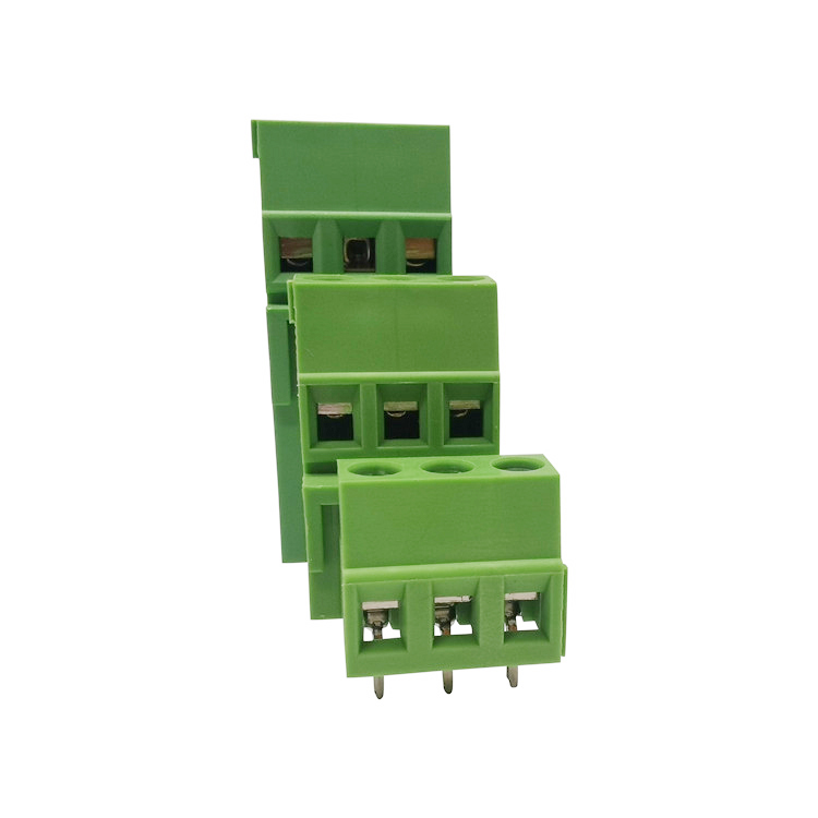
I. What is the Pitch?
Pitch means the distance between the center points of two adjacent pole,
Here is the normally pitch : such as 7.62mm, 9.5mm, 11.0mm, 13.0mm, and 15.0mm.
In isolated HOMNECKS screw terminal blocks, HONG YI ELECTRONIC pitch determines the insulation distance between HOMNECKS terminal blocks,the current carrying capacity, installation space layout, and safety certification standards.
II. Why is Pitch Crucial for High-Current Applications?
1. Creepage Distance and Electrical Safety:
larger pitch means bigger physical distance, for terminal block,HONG YI ELECTRONIC help product to improve creepage distance and clearance, reducing the risk of short circuits.
2. HONG YI ELECTRONIC Determines Current Carrying Capacity: A larger pitch typically means thicker copper components and stronger contact pressure, thus supporting higher currents.
3. HONG YI ELECTRONIC Affects Heat Dissipation and Long-Term Reliability: A suitable pitch helps dissipate heat, reduces temperature rise, and extends product life.
4.Affects Overall Equipment Layout Design: HONG YI ELECTRONIC Pitch directly affects the space utilization of the control cabinet, PCB size, and mounting hole layout.
III. Typical Current Ranges for Different Pitches
7.62mm: 20A–30A
9.5mm: 30A–50A
11.0mm: 50A–75A
13.0mm and above: 75A–150A
Actual selection needs to be confirmed based on specific structural design and material specifications.
IV. Engineering Selection Recommendations
Step 1: Confirm the maximum continuous current.
Step 2: Confirm the system voltage level.
Step 3: Assess environmental factors (humidity, dust, vibration).
Step 4: certification (UL, CE, etc.).
V. Common Misconceptions in B2B Procurement
• Focusing only on price while ignoring pitch
• Considering only rated current while ignoring temperature rise
• Ignoring the impact of long-term load
• Failing to calculate installation space
VI. Summary
Pitch is not only a structural dimensional parameter, but also a key indicator of electrical safety, heat dissipation performance, and system reliability.
For our customer, HONG YI ELECTRONIC choosing the right pitch to reduce after-sales risks, improve product stability, and enhance market competitiveness.
Sourcing electronic parts for industrial manufacturing? Its a big deal.Pluggable PCB terminal blocks are one of the most important components.They balance stable wire connections and easy maintenance—quick to disconnect when you need to fix things.
But there are hundreds of suppliers out there.Finding a reliable pluggable PCB terminal block factory?Super confusing, right?
If you’re stuck on how to choose plug-in terminal blocks,this guide tells you what to look for when picking a manufacturing partner.
1. Check material quality + customization ability
When you’re looking for a direct terminal block factory for wholesale,don’t just go for the cheapest price. Don’t do it.
Good factories use high-grade copper alloy for the contacts.And flame-retardant plastic—like PA66 that meets UL94V-0—for the housing.
Your project might need a specific pitch, color, or silk screen.A good custom pluggable PCB terminal blocks supplier?They have their own R&D and mold departments.So they can handle those custom needs. No hassle.
2. How wide and deep is their product line?
Top manufacturers have a variety of products.For different engineering uses, you know?From standard PCB mount terminal block headers,to high current pluggable terminal blocks for high-power equipment.
A full product line means they have mature production processes.And real technical experience—no fly-by-night operation.
3. Skip middlemen, work directly with the factory
A lot of companies accidentally buy from trading companies, not the actual factory.Bad idea.
Choose a good China PCB mount terminal block manufacturer directly.You’ll get smoother communication.Stricter quality control.And factory-direct prices.That cuts your BOM cost a lot. A real money-saver.
Why Homnecks is your go-to manufacturing partner
Looking for a supplier that checks all these boxes?It takes forever.
But at Homnecks? We’re a leading terminal block factory.We care about quality and innovation—seriously.We make tough, durable pluggable PCB terminal blocks and plug-in terminal blocks.For customers all over the world.
We have our own testing lab. Automated production lines.And prices that are hard to beat.We keep your supply chain running smoothly.And your products working perfectly.
Contact Homnecks’sales team today.Get a competitive quote. Or a custom solution for your specific PCB design.
In the world of power electronics and industrial controls, even one tiny component failure can lead to catastrophic results, ranging from ruined equipment to hazardous electrical fires. When you are sourcing connectors for new control boards, cutting corners on safety is a risk that your business simply cannot afford to take.
While good conductivity is essential, it is not enough on its own. The quality terminal block factory you choose must adhere to rigorous international safety regulations to ensure long-term stability. This guide will walk you through the critical tests and certifications that define a high-performance, reliable terminal block.
1. Flame-Retardant Materials: Your First Line of Defense
During a current overload or a short circuit, the terminal's plastic shell must be capable of self-extinguishing to prevent fire from spreading. Leading factories prioritize the use of PA66 with a UL94V-0 flame rating as a non-negotiable standard for both traditional screw terminals and modern spring terminal blocks.
A high-quality housing is engineered to withstand an 850°C glow-wire test without issue. By stopping fire at the source, these materials keep the entire power cabinet secure, providing a truly safe environment for sensitive electronic components.
2. Why UL and CE Certifications are Non-Negotiable
Selling equipment to North America or Europe without certified parts poses a massive risk at customs and within the legal market. Using UL-listed pluggable PCB terminal blocks ensures that your product has passed tough evaluations for temperature rise, electrical clearance, and tracking index.
Similarly, a CE-certified plug-in terminal block is your essential ticket to the EU market, confirming that your equipment meets the stringent requirements of the Low Voltage Directive (LVD). Without these marks, international expansion becomes nearly impossible.
3. Managing High Current with Temperature Rise Testing
Running a terminal at high load for extended periods requires that the contacts remain cool to avoid thermal failure. For industrial applications demanding high current, it is vital to use pcb mount screw terminal blocks that have been validated through repeated temperature rise cycles.
Our high-grade copper contacts are designed to resist loosening caused by constant heating and cooling. This structural integrity prevents bad connections and ensures zero-failure performance in even the harshest electrical environments.
Homnecks: Safety Built into Every Connection
Homnecks is a globally trusted screwless terminal block manufacturer dedicated to quality and safety. All our products listed on www.homnecksterminal.com undergo rigorous internal lab testing, including plug-in life tests, salt spray tests, and extreme thermal cycling.
No matter how tough your conditions, Homnecks delivers 100% compliant, reliable connections you can trust. Click here to view our certifications and technical specifications—let’s ensure your next project is safe and successful.
Homnecks Isolated terminal blocks vs Homnecks pluggable terminal blocks: Which is better suited for your high-current applications?
I. What is an Homnecks Isolation Terminal Block?
An isolation Homnecks terminal block is a Homnecks terminal structure with a physical isolation barrier, HONGYI ELECTRONIC effectively preventing short circuits between adjacent lines and improving insulation safety. It is commonly used in high-voltage, high-current, and harsh environment scenarios.
Key Features:
• Clear isolation barrier structure for enhanced insulation performance
• High current carrying capacity (typically 30A–150A or more)
• Excellent vibration resistance
• Suitable for power systems, frequency converters, and distribution equipment
II. What is a Homnecks Pluggable Terminal Block?
A pluggable Homnecks terminal block is a modular connection structure, HONGYI ELECTRONIC typically consisting of a male connector and a female connector, facilitating quick plugging and unplugging for maintenance.
Key Features:
• Supports quick installation and replacement
• Saves maintenance time
• Common spacing specifications such as 5.08mm and 7.62mm
• Suitable for medium current applications (typically 10A–40A)
III. Core Comparative Analysis for High Current Applications
Comparison Dimensions:
• Current carrying capacity: Isolated terminals have higher current carrying capacity
• Insulation safety: Isolated terminals are superior
• Vibration resistance: Homnecks Isolated terminals have stronger vibration resistance
• Maintenance efficiency: Homnecks Pluggable terminals have higher maintenance efficiency
• Suitable scenarios: High-power equipment vs. modular equipment
IV. How to Choose for High-Current Applications?
Situations where isolated Homnecks terminal blocks are recommended:
• Current exceeding 50A
• Environments with strong vibrations
• High-voltage power supply systems
• Extremely high safety requirements
Situations where pluggable terminal blocks are recommended:
• Current in the 10A–40A range
• Equipment requiring frequent maintenance or replacement
• Primarily for control signals
• PCB mounting structure
V. Key Technical Indicators for Engineer Selection
Focus on the following during selection:
• Rated Current
• Rated Voltage
• Contact Resistance
• Insulation Material Class (UL94 V-0)
• Operating Temperature Range
• Conductor Cross-sectional Area (AWG)
VI. Conclusion In high-current applications, there is no "best" terminal block, only the "most suitable" choice.
For high-power, high-safety-requirement scenarios, Homnecks isolated terminal blocks are recommended.
For scenarios emphasizing maintenance efficiency and modular design, Homnecks pluggable terminal blocks are preferable.
Proper selection is essential to ensure system safety and long-term stable operation.
Industrial automation and PCB design move fast.Efficiency and reliability matter more than anything.
For decades, screw terminals were the standard.But now applications need faster assembly,especially in tough environments.More engineers and makers are switching to screwless, spring-type terminals.
Why?This guide walks you through wiring with screwless terminal blocks.
1. Faster wiring, lower labor cost
On assembly lines, time is money.Screw terminals need manual tightening.It takes time, and people often over-tighten or under-tighten.
Spring terminals let you just plug wires in.Solid wire or ferrule crimped stranded wire — push it straight in.This cuts wiring time by up to 50%.Lower labor cost is the biggest advantage.
2. Better against vibration
Vibration makes screw connections come loose.That causes breakdowns, repairs, even short circuits.
Spring PCB terminals keep constant pressure on wires.They hold tight in railways, heavy machines, wind turbines.No loosening over time.
3. Spring or screw terminals?
Screw terminals still work great for very high current.But for dense PCBs, vibrating environments, fast assembly —spring terminals are better.
Conclusion
Using screwless terminals in your PCB design improves long-term reliability.
Homnecks is a professional push-in spring terminal block manufacturer. We offer standard and custom solutions.Our engineering team supports your project from start to finish.
Contact us for free samples and technical advice today.
Finding the Right Terminal Block Maker for Your Company
In the electronics business, how good your parts are really impacts how long your product lasts. If you're in charge of buying or designing stuff, picking a good terminal block seller is as important as the circuit design. Here's what to look at when you're checking out who to work with.
Factory or Seller: What’s the difference?
When you're getting parts, you can usually either buy them from someone who sells them from different brands or directly from the company that makes them.
Using a seller: A seller can have different options from different brands and can ship small orders fast. Though if you want a lot of stuff, it might cost you more.
Using a factory: If you buy from the factory, you usually get better prices since you are buying directly. Plus, a factory that only makes terminal blocks will have people who can adjust the product to what you need.
Find a Specialist
Not all factories are the same. If your product is complex, find a maker that is experienced in that area. Makers that know a lot about pluggable tech can make sure everything connects well and lasts a long time.
Why pick us to be your terminal block maker?
We're a top terminal block maker. We're good at giving customers good connections that are certified worldwide. We got it all, from connectors that handle a lot of electricity to small PCB terminals. Because our lines are highly automated, our products are reliable and affordable.
Whether you need a supplier who can reliably ship lots of standard parts or a factory to handle custom designs, we're here to help keep your production going strong.
When you're working on an electronic circuit project, picking the right PCB mount terminal block is super important. It keeps everything safe, reliable, and easy to fix if something goes wrong. There are tons of options out there, so knowing what's what can save you a lot of time and cash. Let's check out some common choices for circuit board designs today.
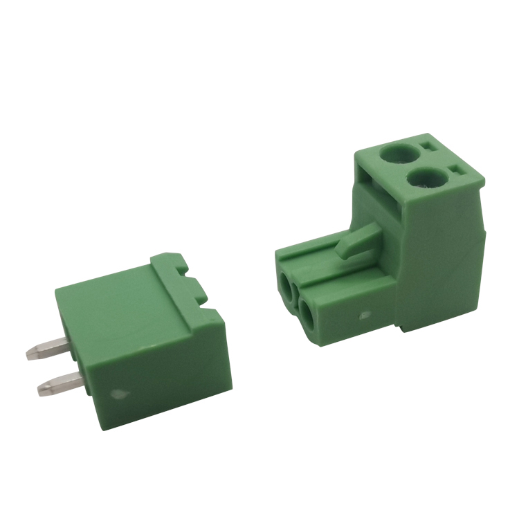
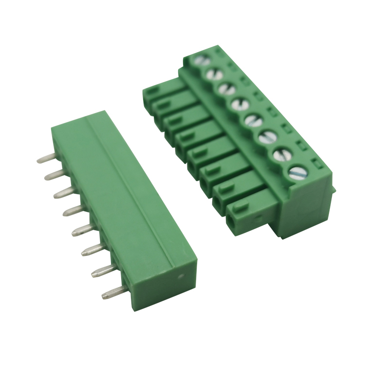
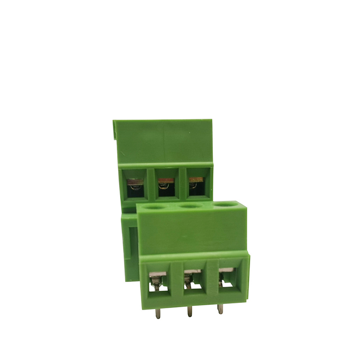
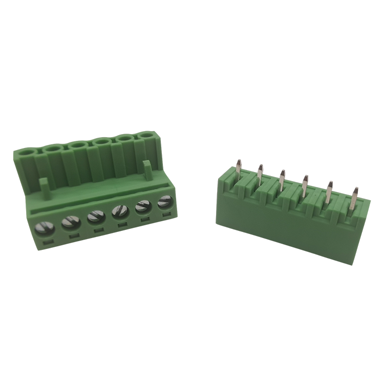
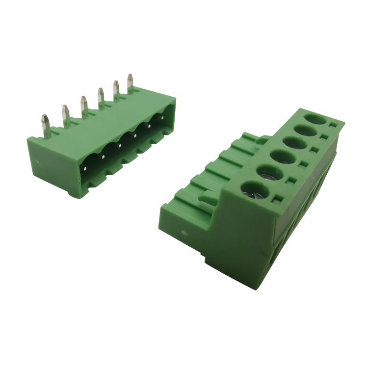
1. Pluggable PCB Terminal Blocks: Super Handy
If your system needs regular check-ups, tests, or part swaps, pluggable PCB terminal blocks are the way to go. They have two parts: a socket that you solder onto the board and a plug where you stick the wires.
Easy Fixes: With these, anyone can quickly disconnect a bunch of wires without messing with each one.
Works Everywhere: You can find these blocks in all sorts of things, like air conditioning systems and factory robots.
2. Quick and Safe: Spring vs. Screwless Terminal Blocks
Want to speed up wiring at work? Check out these options.
Screwless terminal blocks mean no screwdrivers needed! Just push a wire into the hole, and you're done.
Spring terminal blocks use a spring to hold the wire tight. They handle bumps well, so the wires stay put even when things get shaky, like in big machines.
3. Old-School but Good: PCB Mount Screw Terminal Blocks
Even with all the new stuff, the regular screw terminal block is still a solid pick. It clamps down super hard and works with many wire sizes. If you're making power supplies or heavy-duty gear that doesn't need to be plugged and unplugged a lot, these are a cheap and strong choice.
So, whether you're thinking about using spring terminal blocks that can handle a beating, or plug-in blocks for a system that’s easy to take apart, getting the right parts is key to a good project. Always get your stuff from reliable people who make sure everything is top-notch.
Picking the Right Terminal Blocks for Your Industrial Work
This article looks at what you need to think about when picking terminal blocks for industrial use. We'll go over five main things: how much current they can handle, how they connect, where they'll be used, what certifications they have, and how easy they are to maintain and expand. The goal is to help you make your electrical systems safer and more reliable.
Why does picking the right terminal block matter so much?
Terminal blocks are key spots for sending current in things like industrial control systems, distribution boxes, new energy equipment, and automated production lines. If you pick the wrong ones, they can overheat, cause voltage drops, mess up signals, and even shut down your system. They might be small, but they're super important for keeping your electrical systems running smoothly.
I. Figure Out the Real Current You'll Be Using
A lot of projects just look at the rated current of a terminal block, but that's usually based on perfect lab conditions. Things get hotter inside a control cabinet, terminals are packed close together, and there's not much air flow, which all adds to the heat.
It's a good idea to add a 20%-30% buffer to the current capacity when you're choosing. So, if your actual current is 16A, you should go for terminal blocks rated for 20A or more.
II. Pick the Right Connection Type for Your Situation
1. Screw-type: Great for high current and power systems. They lock on really tight, but you need to check the screws every so often to make sure they're still tight.
2. Spring-type: Good for places with a lot of vibration. They keep constant pressure, don't need any upkeep, and are very stable.
3. Plug-in: Ideal for PCBs and modular systems. They're quick to install and easy to swap out.
III. Think About Where They'll Be Installed
If you're using them in places that are hot, humid, dusty, or have corrosive chemicals, go for tinned copper conductors and insulation that's rated UL94 V-0 for flame resistance. If needed, think about using a terminal system with good protection ratings.
IV. Check for the Right Certifications
If you're exporting or working on international projects, you'll usually need UL, CE, IEC, or RoHS certifications. If you don't use certified products, your project might get rejected or you could run into legal trouble.
V. Plan for Maintenance and Future Growth
When you're picking parts, don't just think about what you need right now. Also, think about future expansions, how easy they are to maintain, and how standardized they are. Modular designs can save you money on long-term operation and maintenance.
There's no one-size-fits-all terminal block. The best one is the one that fits your needs the best. By planning for enough current, picking the right connection type, using high-quality materials, and making sure you have the right certifications, you can really make your systems more stable and safe.
 English
 English
 Deutsch
 Español
 عربي
عربي हिंदी
हिंदी


 Contact Us


 IPv6 network supported