Pluggable Terminal Block
Home

terminal block electrical connector

terminal block electrical connector

  • Pluggable PCB terminal block VS screw terminal block VS  spring terminal block: How to choose? Pluggable PCB terminal block VS screw terminal block VS spring terminal block: How to choose?
    Feb 02, 2026
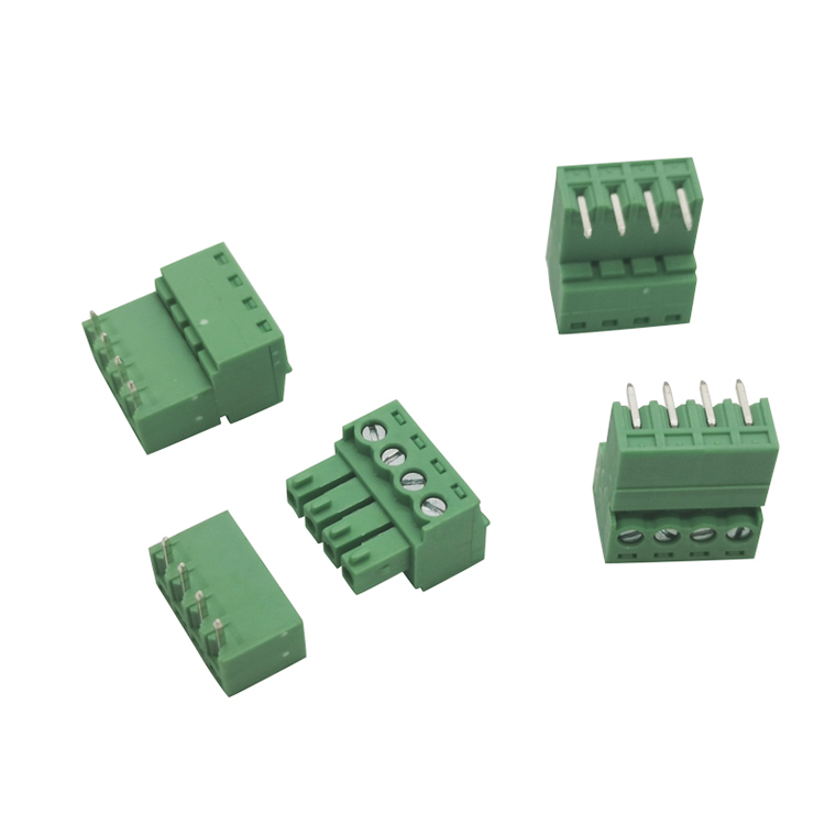
      In industrial control, power systems, automation equipment, and electronic products, terminal blocks are one of the most common and critical connectors.Choosing the right type of terminal block (such as pluggable PCB terminals, screw terminals, or spring terminals) not only affects wiring efficiency but also directly impacts system stability and future maintenance costs.   I. What are Pluggable PCB Terminal Blocks? Pluggable PCB terminal blocks consist of two parts: a plug and a base, allowing for quick insertion and removal without the need for rewiring. This type of terminal block is widely used in modular equipment and industrial control systems. Advantages include: - Fast installation and maintenance - Reliable connection and stable contact - Suitable for PCB mounting - Available in various pitch sizes, such as 3.5mm, 3.81mm, 5.0mm, 5.08mm, 7.5mm, and 7.62mm     II. Screw Terminal Blocks: Characteristics Screw terminal blocks secure wires using screws, resulting in a robust structure. They are one of the most common types of terminals in industrial applications.   Main Features: - Secure wire fixation with strong tensile strength - Suitable for medium to high current applications - Low cost and high versatility - Available in various configurations, including PCB mount screw terminals, 2-pin, 3-pole, etc.   III. Spring/Screwless Terminal Blocks Spring terminal blocks use spring clips to secure wires, eliminating the need for screws and improving assembly efficiency.   Key Advantages: - Fast wiring, reducing labor time - Excellent vibration resistance - Suitable for high-density PCB designs     IV. PCB Mounting Terminals and Barrier Terminal Blocks In applications requiring high insulation distance and safety, barrier terminal blocks are widely used, suitable for power supplies, power control, and industrial equipment.   V. How to Choose the Right Terminal Block? When selecting a terminal block, it is recommended to focus on: 1. Terminal spacing (Pitch) 2. Current and voltage ratings 3. Wiring method (screw/spring/pluggable) 4. PCB mounting method 5. Frequency of future maintenance   Conclusion: Whether it's pluggable terminals, PCB-mounted terminals, or spring terminals, choosing the right terminal solution can significantly improve system stability. As a professional terminal manufacturer and supplier, we can provide customized PCB terminal solutions for our customers.  
    Read More
  • How to Solve Mismatch Issues Between PCB Terminal Blocks and Pins How to Solve Mismatch Issues Between PCB Terminal Blocks and Pins
    Feb 22, 2025
    When working with terminal block connector PCB components,one common challenge is ensuring that the plug and pin align perfectly.A mismatch can lead to poor electrical connections,increased resistance,and even system failures.Whether you're dealing with terminal block electrical connector systems or PCB pin terminal setups,addressing this issue is crucial for maintaining optimal performance.   The first step in resolving a mismatch is to verify the specifications of your PCB terminal connectors.Often,the problem arises from using incompatible components.Check the datasheets for both the plug and pin to ensure they share the same dimensions,pitch,and current ratings.If the PCB terminal blocks you’re using don’t match the pins,consider switching to a compatible model or consulting the manufacturer for guidance.   Another effective solution is to inspect the physical condition of the screw terminal block connector and its pins.Over time,wear and tear can cause deformation or corrosion,leading to alignment issues.Clean the contacts thoroughly and check for any signs of damage.If the pins or connectors are bent or worn outreplacing them with high-quality terminal block connector PCB components can restore proper functionality.   For those designing custom PCB layouts,double-check,the pin spacing and alignment during the design phase.A small error,in the layout of PCB terminal connectors can lead to a significant mismatch.Use CAD tools to simulate the connection and make sure that the PCB pin terminal aligns precisely with the plug.This proactive approach can save both time and resources during assembly.   If the mismatch persists,consider using adapters or intermediary connectors.Many terminal block electrical connector systems offer adapters that can bridge the gap between mismatched components.These adapters are particularly useful when integrating older PCB terminal blocks with newer systems or when working with non-standard pin configurations.   Finally,always test the connection after resolving the mismatch.Use a multimeter to verify the electrical continuity and ensure there’s no excessive resistance.Whether you’re working with screw terminal block connector systems or other types of PCB terminal connectors,thorough testing guarantees a reliable and long-lasting connection.   By following these steps,you canin fact,effectively address mismatch issues among terminal block connector PCB components and pins.This ensures that your electrical systems operate smoothly and with high efficiency.
    Read More
  • The Role of Barrier Terminal Blocks in Electrical Control Cabinets The Role of Barrier Terminal Blocks in Electrical Control Cabinets
    Dec 18, 2024
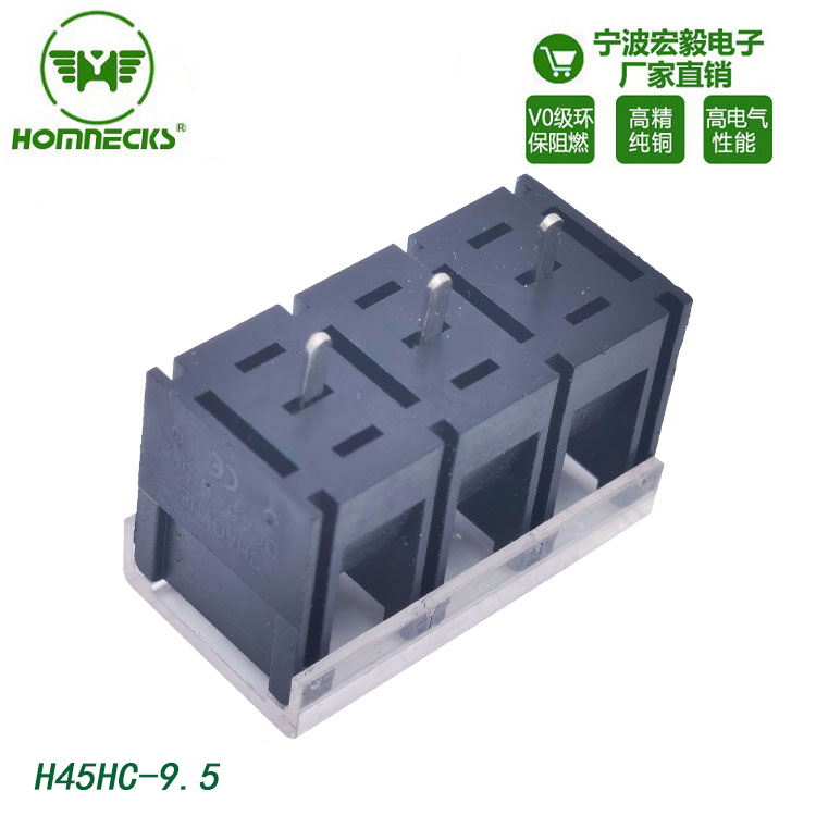
    Electrical control cabinets rely on stable, safe, and maintainable wiring connections. Every terminal choice directly impacts panel reliability, on-site troubleshooting, and long-term equipment uptime. Most procurement and panel engineers focus on current ratings and dimensions only. They often overlook the structural advantages of barrier terminal blocks in harsh industrial environments. Unlike standard terminal blocks, barrier-type units feature independent plastic partitions between each terminal position. This simple structural difference solves many common on-site wiring faults. It also reduces hidden risks for control panels operating for years.   What Are Barrier Terminal Blocks in Panel Wiring? Barrier terminal blocks are insulated connection components with vertical isolation walls between adjacent circuits. Each terminal sits in an independent groove. From on-site engineering experience, these blocks are not for basic signal wiring. They target high-current power loops, motor control circuits, and mains input terminals inside control cabinets. The built-in barriers physically block wire displacement and conductor contact. This improves creepage distance and clearance, two core safety indicators for industrial low-voltage panels. Barrier Terminal Blocks vs Standard Terminal Blocks: Core Differences Many panel faults stem from negligible wiring gaps and vibration-induced wire drift. The table below compares barrier terminal blocks and ordinary non-barrier terminal blocks in actual cabinet application scenarios.   Evaluation Dimension Barrier Terminal Blocks Standard Non-Barrier Terminal Blocks Isolation Structure Independent plastic barrier for each terminal; complete physical circuit isolation No partition between terminals; circuits rely only on wire harness arrangement for isolation Short Circuit Risk Extremely low. Barriers block loose strands and displaced wires High under vibration. Loose copper strands easily cross adjacent terminals Vibration Resistance Excellent. Barriers limit wire shaking offset; fits motor and production line cabinet environments Average. Long-term vibration causes wire drift and hidden short faults Safety Margin Large creepage and clearance distance; compliant with industrial high-voltage safety standards Limited safety margin; prone to arcing under high current and humidity Maintenance Difficulty Low. Single-circuit wiring does not affect adjacent lines during inspection and replacement High. Wire bundles are crowded; easy to touch neighboring wires during operation Typical Application Mains input, high-current power distribution, motor control loops Low-current signal lines, communication wiring, low-power auxiliary circuits     Barrier Terminal Blocks vs DIN Rail Terminal Blocks: Selection Guide for Engineers DIN rail blocks dominate cabinet wiring, but barrier blocks show irreplaceable value in specific high-reliability scenarios. The following comparison helps procurement engineers make cost-effective model selections. Parameter Barrier Terminal Blocks DIN Rail Terminal Blocks Mounting Method Panel surface mounting DIN rail mounting Current/Voltage Adaptation Excellent for 250–600V high-current power circuits Suitable for most low-voltage control and signal circuits Wiring Density Moderate pitch, prioritizes safety over density High density, saves cabinet space On-Site Stability Strong anti-vibration, anti-displacement performance Stable for static cabinets; weaker for long-term vibration scenarios Service Life Long lifespan, resistant to high temperature and dust erosion Standard lifespan, suitable for conventional indoor environments Cost Positioning Medium cost, high safety return Low to medium cost, cost-effective for universal use     4 Key Practical Values of Barrier Terminal Blocks in Control Cabinets    1. Eliminate Vibration-Induced Hidden Faults Most on-site panel short faults do not come from product quality problems. They occur from tiny wire offset caused by long-term equipment vibration. Production line machinery, fans, and motors generate continuous vibration. Ordinary terminal block wires gradually shift. Fine copper strands may contact adjacent circuits, causing instantaneous short circuits and equipment shutdown. Barrier terminal blocks fix this problem physically. Isolation walls limit wire shaking range. Even with slightly loose screws, wires cannot cross adjacent terminals.   2. Improve Panel Safety Margin for Harsh Environments Factory humidity, dust, and temperature changes reduce insulation performance between terminals. Narrow gaps of standard blocks easily accumulate dust and moisture, leading to creepage and arcing. Barrier blocks extend insulation distance. They effectively avoid surface discharge under high humidity and high temperature. For outdoor cabinets and workshop equipment, this greatly reduces fire and burnout risks.   3. Simplify On-Site Maintenance and Upgrades During annual inspection and circuit modification, engineers often need to disconnect single loops. Standard terminal blocks have dense wiring. One wire misoperation may scratch adjacent lines or cause accidental contact. Independent barrier grooves achieve single-circuit independent operation. Maintenance personnel can replace and test target wires safely without affecting other normal circuits.    4. Standardize Wiring and Improve Panel Grade For OEM equipment and automated production lines, standardized wiring directly affects product competitiveness. Barrier blocks arrange wires neatly. They avoid messy crossing of power and signal lines. From project delivery experience, panels using barrier blocks for power circuits have lower after-sales failure rates. They pass customer factory safety audits more easily.   FAQ    Q1: Are barrier terminal blocks required for every circuit inside the control cabinet?   A: No. They are overkill for low-current signal wiring and static indoor cabinets with stable ambient conditions. We recommend barrier terminal blocks for mains input points, high-current distribution circuits, motor control loops, and cabinets mounted on vibrating machinery. Match terminal types by circuit function to balance safety and total project cost.   Q2: What is the main failure risk barrier terminal blocks prevent that standard terminals cannot? A: The biggest hidden risk is stray copper strands and shifted conductors touching neighboring terminals. Field technicians often see loose wire strands escaping from stripped cable ends. Vibration slowly pushes these fine copper pieces across terminal gaps. Standard terminals have no physical stop. Barrier walls block this cross-contact, stopping intermittent short circuits before they trigger unexpected machine stops.   Q3: Can I replace DIN rail terminal blocks with barrier terminal blocks directly in existing cabinet designs? A: Not always. Mounting style is the main constraint. Barrier terminal blocks are usually panel-mounted, while standard DIN rail terminals clip onto DIN rails. You will need to reserve flat panel space and adjust your BOM. For retrofits, keep DIN rail terminals for signal circuits. Swap only high-power, vibration-prone circuits to barrier blocks for best ROI.
    Read More
  • Materials for 90-Degree Plug for PCB Connectors
    Sep 05, 2024
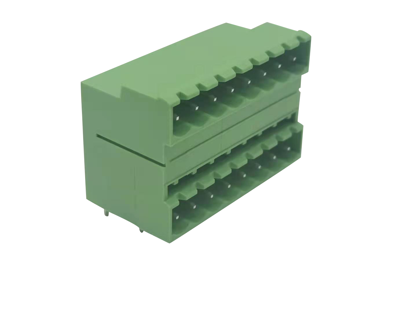
    90-degree PCB plug connectors are widely used in control cabinets, automation devices, and compact PCB modules. Their right-angle design saves cabinet space and standardizes internal wiring layouts. Most design and procurement engineers focus only on pin pitch, current rating, and mounting type. Few pay enough attention to plug housing materials. From field troubleshooting experience, material defects cause most long-term plug failures. These include thermal deformation, dimensional loosening, poor insulation, and brittle cracking under vibration. The housing material directly determines heat resistance, mechanical stability, moisture adaptability, and service life. Choosing the wrong material leads to intermittent connection faults, reflow soldering failure, and high after-sales rates. This guide breaks down the four most common materials for 90-degree PCB plugs. It includes verified parameter comparisons, field pros and cons, and clear selection rules for industrial control projects. Why 90-Degree PCB Plug Material Selection Matters Right-angle PCB plugs face unique working stress compared with straight plugs. The 90-degree structure bears repeated wire pulling and lateral vibration. The bending corner accumulates heat during high-current operation. SMT and wave soldering processes also bring instant high-temperature impact. Low-grade materials deform easily after soldering. They cause pin misalignment and poor mating. In humid and dusty industrial workshops, unqualified materials lose insulation performance faster, bringing hidden short-circuit risks. 4 Main Materials for 90-Degree PCB Plugs: Full Parameter Comparison PA66, PBT, LCP, and PA9T dominate industrial 90-degree PCB plug manufacturing. The table below compares core industrial parameters based on actual soldering processes and field operation data. Performance Parameter PA66 (Nylon 66) PBT LCP PA9T Continuous Working Temperature -40°C to 105°C -40°C to 120°C -55°C to 240°C -40°C to 150°C Reflow Soldering Resistance Max 230°C, easy softening 240°C stable, slight shrinkage 260°C+ fully compliant 250°C high stability Moisture Absorption Rate 1.0%–3.0% (high, easy deformation) ≤0.1% (ultra-low) ≤0.02% (negligible) ≤0.3% (low) Vibration & Impact Resistance Excellent toughness, anti-crack Good rigidity, slightly brittle High rigidity, anti-deformation Balanced toughness & rigidity Flame Retardant Grade UL94 V-0 (standard) UL94 V-0 UL94 V-0 high grade UL94 V-0 Relative Material Cost Low Medium High Medium-High Best Industrial Application Wave solder, low-cost signal plugs General industrial & automotive connectors SMT high-temperature precision plugs High-reliability power & signal plugs Material Pros & Cons for 90-Degree PCB Plugs (Field Perspective) This simplified table helps engineers and purchasers quickly screen materials during BOM confirmation, avoiding over-specification or insufficient performance. Material Key Field Pros Key Field Cons PA66 Low procurement cost, strong toughness, resistant to impact and bending, widely available for mass production High moisture absorption causes dimensional shift in humid environments; poor high-temperature resistance for SMT reflow processes PBT Ultra-low water absorption, stable size, good chemical and UV resistance, balanced cost and performance Slightly brittle under strong vibration; easy to crack after long-term repeated plugging LCP Extreme high-temperature resistance, zero deformation after reflow soldering, ultra-stable insulation, best precision retention High material cost, strict molding process requirements, not cost-effective for ordinary low-power circuits PA9T High heat resistance, low moisture absorption, excellent vibration resistance, stable for both power and signal circuits Higher price than PA66 and PBT, mainly used for mid-to-high-end industrial equipment Practical Material Selection Rules for 90-Degree PCB Plugs 1. Select by Soldering Process For wave soldering mass production, PA66 and PBT are fully qualified. They balance cost and basic heat resistance. For SMT reflow soldering with 260°C high-temperature impact, only LCP and PA9T can avoid housing deformation and pin offset. PA66 will soften and cause assembly failure. 2. Select by On-Site Environment Humid workshop environments avoid pure PA66. Its high water absorption changes plug size, leading to loose mating and poor contact. Vibration-prone equipment such as motor control cabinets prioritizes PA66 or PA9T. Their toughness prevents shell cracking. High-temperature industrial cabinets choose PBT, PA9T or LCP to resist thermal aging. 3. Select by Circuit Type Ordinary low-current signal circuits use PA66 or PBT for cost control. High-current power circuits and high-precision signal acquisition circuits require PA9T or LCP. Stable insulation and size consistency avoid drift faults.   FAQ for 90-Degree PCB Plug Material Selection Q1: Why do some 90-degree PCB plugs deform after SMT reflow soldering? Most deformation issues come from mismatched housing materials. Standard PA66 cannot withstand 260°C reflow temperature. It softens and shrinks after heating, causing pin misalignment and poor mating. For SMT processes, always specify LCP or PA9T materials to ensure zero deformation after soldering.   Q2: Which material is the most cost-effective for general industrial control cabinet projects? PBT is the best balanced option for most conventional projects. It features ultra-low moisture absorption, stable dimensional performance, and qualified heat resistance. It avoids PA66’s humid-environment deformation risks and does not require the high budget of LCP materials, perfectly fitting mass-produced control cabinet signal and low-power circuits.   Q3: Is LCP material necessary for all high-temperature PCB plug applications? No. LCP is mandatory only for ultra-high-temperature reflow soldering and high-precision equipment requiring strict dimensional stability. For regular high-temperature working scenarios below 150°C, PA9T provides sufficient heat resistance and vibration resistance at a lower cost. Engineers can match materials according to actual process and environmental requirements to avoid over-specification waste.
    Read More
leave a message
If you are interested in our products and want to know more details,please leave a message here,we will reply you as soon as we can.
Submit

Home

Products

whatsApp

contact