Comparing screw, spring, screwless, and pluggable PCB terminal blocks? This article breaks down cost, assembly speed, vibration resistance, and field serviceability to help you choose.
Walk through any industrial electronics production line, and you will see PCB terminal blocks on nearly half of all control boards and power modules.
Most design and procurement teams treat terminal blocks as simple commodity parts. They often pick the lowest-cost option and move on with the BOM. But this casual selection leads to real field issues.
The gap between screw, spring, screwless, and pluggable terminal blocks goes far beyond component cost. It impacts production efficiency, long-term equipment reliability, vibration tolerance, and years of on-site maintenance work.
This practical industrial comparison guide covers the four mainstream terminal block types. We use real manufacturing and field service perspectives to help you select the best option for your control cabinet and industrial equipment projects.
Overview of 4 Main PCB Terminal Block Types
Each terminal block design serves distinct production and field scenarios. Before detailed comparisons, we clarify the core working principles and industry search terms for each type.
Screw Terminal Blocks
This is the most traditional and widely used design. A metal clamp plate is driven by screw torque to firmly fix stripped wires. It features mature technology and full-spec coverage. Common industry search terms include “PCB screw terminal block” and “screw terminal block connector”.
Spring Terminal Blocks
It replaces manual screw locking with a built-in spring cage. Wires are inserted against spring tension and fixed automatically. Most models require no tools, delivering fast and stable wiring.
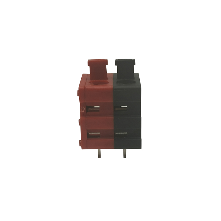
Screwless Terminal Blocks
An upgraded iteration of spring-type structures, mostly operated by levers or push buttons. Open the lever, insert the wire, and close to lock. The keywords “screwless terminal block” and “screwless terminals” cover this full product series, ideal for high-efficiency wiring scenarios.
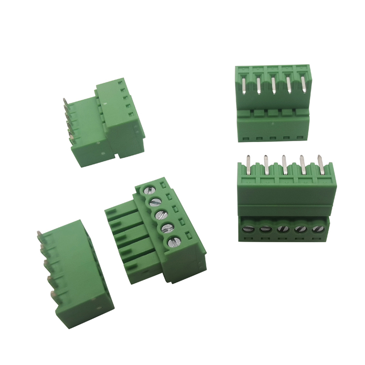
Pluggable Terminal Blocks
A two-piece separable structure, consisting of a PCB-soldered fixed header and a detachable wire plug. The entire wire harness can be plugged and unplugged as a whole without rewiring single cores. Popular search terms: “pluggable PCB terminal block” and “pluggable terminal block connector”.
Barrier Terminal Blocks
A specialized screw-type variant with independent plastic isolation barriers between adjacent poles. It provides sufficient creepage and clearance distance, tailored for high-voltage industrial power distribution scenarios. “Barrier screw terminal block” is a high-volume industrial search term.
Terminal Block Full-Dimension Comparison Table
For quick selection and BOM evaluation, we summarize core indicators including cost, assembly efficiency, vibration resistance, field maintainability, and wire compatibility of all mainstream models.
Terminal Block Type
Unit Cost Level
Assembly Speed
Vibration & Shock Resistance
Field Serviceability
Wire Gauge Tolerance
Best Industrial Application Scenarios
Screw Type
Lowest
Slowest (tool-dependent)
Average (prone to loose over time)
Poor (full wire re-termination required)
Wide (24–12 AWG, high tolerance)
High-volume low-cost equipment, static indoor control cabinets, cost-sensitive projects
Spring/Screwless Type
Medium (+20%~50% vs screw type)
Very fast (tool-free wiring)
Excellent (self-locking anti-vibration)
Medium (fast re-wiring, no integral disassembly)
Narrow (fixed diameter range only)
Mass production lines, motor equipment, vehicle-mounted/railway industrial devices
Pluggable Type
Highest (dual-part structure)
Fast wiring, slow initial assembly
Good (stable mating structure)
Excellent (one-click harness disassembly)
Depends on plug internal termination type
Field-maintained equipment, modular control boards, replaceable industrial modules
Barrier Screw Type
Medium-High
Slow manual assembly
Good (stable pressure-bearing structure)
Medium
Wide, suitable for high-current thick wires
High-voltage power distribution, motor control, new energy inverter equipment
Cost Analysis: Lowest Component Cost Does Not Equal Lowest Total Cost
Screw terminal blocks have the lowest single-unit cost. The mature structure and standardized production process make them the most cost-competitive option for high-volume BOM matching.
Spring and screwless terminal blocks cost 20% to 50% more per pole. The precision spring steel parts and customized plastic shells raise manufacturing costs.
Pluggable terminal blocks are the most expensive. They adopt a dual-body structure of header and plug, with stricter mating tolerance requirements.
From on-site engineering perspective, component unit cost is misleading. Screw blocks require manual screwdriver operation for each pole. For thousands of mass-produced boards, the accumulated labor costs far exceed the price difference of spring or screwless blocks. Choosing slightly more expensive tool-free models effectively reduces overall production costs.
Assembly Speed: Tool-Free Structures Dominate Mass Production
Assembly efficiency is the biggest advantage of non-screw terminal blocks.
For screw terminal blocks, every independent pole requires repeated operations: wire insertion, screwdriver tightening, and torque inspection. A 12-pin terminal block needs 12 independent tightening steps. This severely restricts beat speed on automated and manual assembly lines.
Spring terminal blocks support direct wire insertion and automatic clamping. Lever-style screwless blocks only need simple opening, wire feeding, and closing actions. Each wiring operation takes less than one second.
For high-volume industrial and commercial equipment, the labor savings brought by spring and screwless blocks completely offset the higher component cost. For small-batch customized cabinet equipment, the efficiency gap is negligible.
Vibration Resistance: The Most Underrated Reliability Indicator
Vibration and shock resistance directly determine the long-term stable operation of industrial equipment, which is easily ignored in early design.
Traditional screw connections suffer from micro-relaxation after long-term vibration. The clamping force slowly decays over thousands of operating hours, causing poor contact or open circuits. This fault is extremely common in motor drives, mobile mechanical equipment, and vehicle-mounted control cabinets.
Spring and screwless terminal blocks feature passive self-tightening structures. Vibration will not loosen the connection; instead, it makes the wire fitting more compact. This is why they are standard for railway, automotive, and heavy industrial vibration scenarios.
Screw blocks are only suitable for static indoor equipment with stable operating environments.
Field Serviceability: Pluggable Blocks Completely Optimize Maintenance
On-site board replacement and fault maintenance are the core pain points of after-sales engineering.
When screw or spring terminal block boards fail, technicians need to disassemble, mark, and sort each wire one by one. After replacing the new board, all wires must be re-terminated and calibrated. A 16-pin board replacement takes nearly 20 minutes, with high risk of wrong wiring and secondary faults.
Pluggable terminal blocks change the maintenance logic. The overall wire harness plug is separated from the PCB header in one step. Replace the new board and re-plug the integral harness. The whole process takes only 2 minutes, with zero risk of wire sequence errors.
The only tradeoff of pluggable structures is larger vertical board height. For control cabinets with limited internal space, the outline size must be verified in advance.
Wire Adaptability & High-Voltage Compliance Scenarios
Screw terminal blocks have the strongest wire compatibility. The adjustable clamping structure adapts to 24 AWG to 12 AWG wires, fitting different wiring specifications in multi-region installation scenarios.
Spring and screwless models have fixed wire diameter adaptation ranges. Ultra-thin wires cannot be clamped firmly, and ultra-thick wires cannot be inserted. Designers must strictly check the datasheet parameter range.
For high-voltage scenarios above mains voltage, conventional small-pitch terminal blocks cannot meet IEC and UL creepage and clearance standards. Barrier terminal blocks solve this problem through isolated plastic barriers and 7.5mm/7.62mm large pitch design, which is the mainstream compliant choice for power distribution and new energy inverter equipment.
Mainstream Manufacturer Selection & Supply Reference
Two brands dominate the global industrial terminal block market: Phoenix Contact and Degson.
Phoenix Contact is a German high-end brand with comprehensive product lines and high global recognition, widely used in high-standard industrial projects in Europe and America.
Degson provides full-spec, cost-effective terminal block products, with strong supply chain advantages in cost-sensitive global projects and Asian markets.
Both brands cover screw, spring, screwless, pluggable, and barrier series. When customizing non-standard parts, prioritize models compatible with these two mainstream standards to ensure secondary supply availability and avoid supply chain risks.
Practical Engineering Selection Rules
There is no universal best terminal block. The optimal choice depends on your equipment’s operating environment, production mode, and after-sales maintenance mode.
•Cost-sensitive high-volume static equipment: Choose screw terminal blocks for maximum cost performance.
•Mass production or vibration-prone equipment: Choose spring or screwless terminal blocks to improve efficiency and long-term reliability.
•Field-maintained modular equipment: Choose pluggable terminal blocks to greatly reduce after-sales labor costs and wiring faults.
•High-voltage power distribution and industrial power equipment: Choose barrier screw terminal blocks to meet safety isolation standards.
FAQs: Common Terminal Block Selection Questions From Engineers
Below are five frequently asked questions about PCB terminal block types, focused on real industrial design, production, and field maintenance concerns.
1. Are spring terminal blocks more reliable than screw terminal blocks for industrial equipment?
Spring terminal blocks deliver better long-term reliability in dynamic industrial environments. Screw-type blocks can lose clamping force over time due to equipment vibration and thermal cycling, leading to intermittent connection faults. Spring and screwless blocks maintain consistent clamping pressure passively, making them more reliable for motors, moving machinery, and vehicle-mounted control systems. For static indoor cabinet applications, properly torqued screw blocks remain sufficiently reliable.
2. Is it worth upgrading to pluggable terminal blocks for standard control boards?
Pluggable terminal blocks are worthwhile if your equipment requires on-site servicing, repair, or board replacement. Although they cost more and require extra vertical PCB space, they cut field maintenance time from 20+ minutes to under 2 minutes per board. They also eliminate human error from manual wire re-termination. For fixed, non-serviceable OEM boards with no after-sales replacement needs, standard screw or spring blocks are the more cost-effective option.
3. What is the biggest risk of using mismatched wire gauge on spring terminal blocks?
Spring terminal blocks have a strict fixed wire diameter range. Using overly thin wires causes insufficient clamping force, resulting in loose contacts and signal dropout under minor vibration. Using overly thick wires cannot fully insert into the spring cage, leading to exposed copper and short-circuit hazards. Unlike screw terminal blocks with high wire tolerance, spring models offer almost no on-site adjustment margin — always match the wire gauge to the datasheet specs.
4. When should I choose barrier terminal blocks instead of regular screw blocks?
Choose barrier terminal blocks for mains-level and high-voltage power distribution, motor control, and inverter designs. The isolated plastic barriers between poles extend creepage and clearance distances, fully complying with IEC and UL industrial safety standards. Regular screw terminal blocks with small pitches cannot meet high-voltage insulation requirements and face safety risks during long-term operation.
5. Do tool-free screwless terminal blocks reduce production quality stability?
No, standardized screwless lever-type terminal blocks improve production consistency. Screw block quality relies heavily on worker operation — inconsistent torque leads to uneven clamping force. Screwless structures adopt mechanical fixed positioning, ensuring every wire obtains identical clamping tension. This reduces batch production defects and is ideal for high-volume automated assembly lines.
Stuck selecting PCB terminal blocks for your control cabinet or industrial equipment design? You’re not alone.
Most electrical and procurement engineers face the same issue. The BOM only lists “terminal block” with no specific specs. With dozens of types, pitch sizes, and pole counts available, picking the wrong model leads to assembly delays, field failures, and rework costs.
This hands-on guide skips textbook theory. It delivers real-world engineering knowledge to help you select the ideal PCB terminal block for industrial control boards, power supplies, and drive equipment. We’ll cover core types, standard pitch sizes, key selection rules, and common field mistakes to avoid.
What Is a PCB Terminal Block & Why It Matters
A PCB terminal block is a modular board-mounted connector. It secures electrical wires to a printed circuit board without soldering individual wires directly.
The working principle is simple. Wires are inserted into the block, then fixed via screw, spring, or lever clamping structure. Power and signals transmit through internal pins to the PCB.
While the structure looks basic, the clamping method and dimensional specs determine assembly efficiency, vibration resistance, current carrying capacity, and field serviceability.
Three core parameters define all PCB terminal blocks:
•Clamping mechanism: Screw, spring, screwless, or pluggable
•Pitch size: Center-to-center distance between adjacent poles (mm)
•Pole count: Number of independent circuits per block
Getting any parameter wrong causes practical issues. Poor fit with equipment housings, insufficient current tolerance, or slow production line assembly are all common on-site problems from improper selection.
PCB Terminal Block Types: Pros, Cons & Industrial Use Cases
Four types of terminal blocks dominate industrial cabinet and equipment design. Each has clear application boundaries. We’ve summarized their on-site advantages, drawbacks, and typical scenarios for quick comparison.
Terminal Block Type
Working Principle
Key Advantages (On-Site)
Common Drawbacks
Typical Industrial Applications
Screw Type
A metal plate presses and fixes stripped wires via screw torque
Low cost, ultra-reliable, compatible with wide wire gauge ranges, easy on-site maintenance
Slow manual assembly; loose connections easily occur under long-term vibration if torque is unstandardized
General power boards, fixed control cabinets, low-cost industrial equipment
Spring Type
Built-in spring cage clamps wires automatically after insertion
Tool-free quick wiring, excellent vibration resistance, stable long-term connection
Narrow wire gauge adaptation range, higher unit cost than screw types
Transportation equipment, vibration-prone machinery, industrial automation control boards
Screwless (Lever/Button)
Open via lever/button, insert wire, close to lock tightly
Zero tools needed, fastest field wiring, suitable for high-volume wiring scenarios
Higher procurement cost, limited applicability for ultra-thick wires
Building automation, lighting control systems, on-site batch wiring projects
Pluggable Type
Split structure: fixed PCB header + detachable wire plug
Board and wire harness separable, ultra-convenient for equipment maintenance and replacement
Higher cost, requires precise pitch matching for mating
Field-serviced equipment, replaceable control boards, modular industrial devices
Barrier Type
Independent plastic barrier between poles, screw + washer wire clamping
Strong insulation, high voltage resistance, durable heavy-duty performance
Large board footprint, bulky structure, slow assembly
Power distribution equipment, motor control boards, high-voltage industrial systems
Common Pitch Sizes: Specs, Capacity & Application Scenarios
Pitch size is the core dimension affecting board layout, wire compatibility, current load, and insulation clearance. For industrial design, pitch selection directly determines equipment safety and space utilization.
Standard Pitch Size
Core Performance Features
Current & Voltage Level
On-Site Application Scenarios
2.54mm (0.1")
Minimum standard pitch, compact footprint
Low current, signal level only
Small signal control boards, sensor signal transmission, space-constrained low-power equipment
3.5mm / 3.81mm (0.15")
Most versatile industrial pitch, balanced size and performance
Medium low current, general industrial voltage
Universal industrial control boards, PLC peripheral modules, standard cabinet signal and power integration circuits
5.0mm / 5.08mm (0.2")
Supports thicker wires, higher load capacity
Medium current, conventional power voltage
Switching power supplies, inverters, motor drive boards, industrial power modules
7.5mm / 7.62mm
Maximum creepage & clearance distance, strong insulation
High current & high voltage
High-power industrial equipment, heavy machinery control, high-voltage power distribution terminals
Field engineer quick rule: For 90% of general industrial PCB designs, choose 3.81mm or 5.08mm pitch. Select 2.54mm only for compact signal circuits, and 7.5mm+ exclusively for high-power, high-voltage loads.
Pole Count Selection: Match Circuit Design & On-Site Maintainability
Pole count refers to the number of independent circuits in one terminal block. Standard industrial stock models range from 2P to 16P, with 2/3/4/6/8/12P being the most common and readily available.
Basic pole count matching logic:
- 2P: Single circuit (positive/negative, line/neutral)
- 3P: Power circuit with ground wire or three-phase single loop
- 4P+: Multi-group signal circuits or three-phase + ground integrated circuits
Two practical on-site tips for pole count selection:
First, do not over-rely on single high-pole blocks. A 12P block can be replaced with two 6P blocks. Split design makes on-site wiring, troubleshooting, and component replacement much easier.
Second, prioritize modular stackable models. Most screw and pluggable terminal blocks support free combination of 2P/3P/4P units. This flexible combination adapts to multi-SKU equipment with different I/O counts and reduces inventory pressure.
Step-by-Step Terminal Block Selection Flow for Industrial Design
Follow this engineering-oriented selection process for new board designs to avoid matching errors:
1. Confirm current and voltage load first
Load parameters determine pitch size. Below 10A low-voltage scenarios apply 2.54mm–3.81mm pitch. For currents above 15A, strictly choose 5.08mm or 7.62mm high-load pitches to avoid overheating and burnout.
2. Verify wire gauge compatibility
Check the datasheet’s wire gauge range (most cover 12–24 AWG). Focus on the maximum on-site wire thickness to ensure full clamping and avoid poor contact from mismatched gauges.
3. Match production and assembly conditions
For mass production and high-efficiency wiring projects, select spring or screwless terminal blocks to cut manual working hours. For cost-sensitive standard equipment, traditional screw blocks are the most cost-effective option.
4. Consider field maintenance requirements
If the control board needs regular replacement, debugging, or after-sales maintenance, invest in pluggable terminal blocks. The wire harness stays fixed on-site, and only the PCB is replaced, greatly shortening maintenance downtime.
5. Check equipment vibration environment
Motor equipment, mobile machinery, and vehicle-mounted industrial devices cannot use ordinary screw terminal blocks (prone to loose wires from vibration). Spring and screwless clamping structures provide persistent fastening force for stable long-term operation.
6. Confirm supply availability
Stick to mainstream models from reliable brands like Phoenix Contact and Degson. Prioritize standard pitch and pole count stock parts. Custom non-standard specs lead to long lead times and inconvenient after-sales replacement.
FAQs About PCB Terminal Blocks for Industrial Designs
Below are five frequently asked questions from control cabinet designers and equipment procurement engineers, focusing on real on-site selection and wiring pain points.
1. What is the most universal PCB terminal block pitch for industrial control boards?
3.81mm and 5.08mm are the two most universal pitch sizes for industrial applications. 3.81mm works for most signal and low-power circuits under 10A, while 5.08mm covers medium-current power circuits for inverters, power supplies, and motor drives. These two sizes fit nearly all standard control cabinet layouts and avoid space or current load issues for general-purpose designs.
2. Are pluggable terminal blocks worth the extra cost?
Pluggable terminal blocks deliver clear value for field-serviced equipment. Though more expensive than standard screw blocks, they separate the wire harness from the PCB, allowing fast board replacement and on-site debugging without rewiring. They effectively reduce equipment downtime and after-sales labor costs, making them cost-effective for modular industrial devices and frequently maintained control systems.
3. Which terminal block type is best for high-vibration industrial environments?
Spring and screwless terminal blocks are the top choices for vibration-prone scenarios such as motor equipment, mobile machinery, and vehicle-mounted industrial devices. Traditional screw terminal blocks tend to loosen after long-term vibration due to torque decay. Spring-loaded clamping structures provide constant, stable fastening force to prevent loose wiring and intermittent circuit faults.
4. Can I mix different pitch sizes on the same PCB?
It is not recommended. Similar pitch sizes (3.5mm vs 3.81mm, 5.0mm vs 5.08mm) look visually identical but have non-interchangeable pin spacing. Mixed pitches will cause mating failure for pluggable headers, lead to assembly errors, and even result in short circuits. Always unify pitch specs for consistent wiring and assembly compatibility on a single board.
5. What pole count should I choose for custom industrial PCBs?
Prioritize standard stock pole counts (2/3/4/6/8/12P) and avoid special odd-pin models. For complex multi-circuit boards, split a single high-pole block (e.g., 12P) into multiple low-pole modular blocks. This design improves on-site wiring clarity, simplifies troubleshooting, and supports flexible combination for multi-SKU equipment to reduce inventory costs.
6 Common On-Site Selection & Wiring Mistakes to Avoid
Most terminal block failures occur not in the lab, but in long-term field operation. These are the most frequent engineering errors:
- Ignoring standard wire strip length: Too short stripping causes insufficient clamping; too long stripping exposes bare copper, bringing short-circuit risks. Always follow the datasheet’s recommended strip size.
- Mixing similar pitch sizes: 3.5mm and 3.81mm blocks look identical visually, but mismatched pitches cause pluggable header mating failure and assembly scrap.
- Reserving insufficient wiring space: Neglecting wire bending radius leads to no operating space for on-site wiring when terminal blocks are too close to housings or capacitors.
- Overtightening screw terminals: Excessive torque breaks wire strands and cracks plastic housings. Strictly follow the standard torque value in the official datasheet.
- Unmatched pole count redundancy: Blindly using high-pole blocks causes wiring chaos and wasted board space.
- Ignoring vibration resistance grade: Using ordinary blocks for vibrating equipment leads to intermittent circuit failures after months of operation.
Final Engineering Takeaway
PCB terminal blocks are humble but critical components for industrial control equipment. They are the key interface between PCBs and on-site electrical wiring.
Improper selection does not cause immediate failure in testing. It triggers hidden troubles like loose wiring, poor contact, and equipment shutdown after long-term field operation. The time spent on precise terminal block selection in the design stage is far less than the cost of on-site after-sales maintenance and product rework.
 English
 English
 Deutsch
 Español
 عربي
عربي हिंदी
हिंदी

 Contact Us



 IPv6 network supported