English
 English
 Deutsch
 Español
 عربي
عربي हिंदी
हिंदी


The Right Pin Header is a very classic and important design feature of this type of terminal, which directly affects the usage method of the terminal and the reliability of its final application.
Item No :
H2EDGCR-2.5Payment :
T/TProduct Origin :
ChinaColor :
green ,we can also make other color if meet moqH2EDGCR-2.5 Pluggable terminal block Right Pin Header
The part used for soldering to the circuit board and establishing electrical connection.
Right Pin Header refers to the pin insertion part that is not straight, but has been bent and shaped at a specific angle (usually 90 degrees).
1.Type and Pole
Type: Pcb Pluggable Screw Terminal Block
The design of the curved needle is not arbitrary; it primarily aims to address issues related to space and assembly. Its core advantages include:
Achieve horizontal installation
Straight pin terminal: After soldering, the terminal is perpendicular to the circuit board. This means that all wires are vertically led out from above the circuit board, occupying a large amount of vertical space.
Bent pin terminal: After soldering, due to the 90-degree bend of the pin, the terminal body is parallel to the circuit board. Wires can be inserted from the horizontal direction, greatly saving vertical space (height) inside the device. This is crucial for compact devices with limited housing height.
Provide strain relief
When the wire is horizontally inserted, if it is subjected to pulling or vibration, the force will directly act on the main body of the terminal and the solder joint.
The "L" shape of the bending pin itself acts as a buffer, better able to withstand and distribute these stresses, reducing direct damage to the solder joints and thus enhancing the mechanical reliability of the connection.
Easy to wire and maintain
The horizontally arranged wires are very neat, facilitating wiring, identification, and inspection. In a dense wiring environment, it is much more convenient to access wires from the side than from above.
During maintenance, technicians can easily access and operate the plug-in and plug-out parts without being obstructed by the dense cables above.
Compatible panel cut-out
In many designs, terminal blocks are installed at the opening of the equipment panel, allowing users to connect wires from the outside. The bent pin design enables the entire terminal block to be flatly attached to the inside of the panel, while the insertion pins are soldered to the internal circuit board through holes on the panel. This is a very standard and practical installation method.
Pole:
| 2 pin terminal block | 3 pin terminal block | 4 pin terminal block | 5 pin terminal block | 6 pin terminal block | 7 pin terminal block |
| 8 pin terminal block | 9 pin terminal block | 10 pin terminal block | 11 pin terminal block | 12 pin terminal block | 13 pin terminal block |
| 14 pin terminal block | 15 pin terminal block | 16 pin terminal block | 17 pin terminal block | 18 pin terminal block | 19 pin terminal block |
| 20 pin terminal block | 21 pin terminal block | 22 pin terminal block | 23 pin terminal block | 24 pin terminal block |
2.Material Of Pluggable Terminal Block
| Housing | PA66, UL94V-0 |
| Pin header | Copper alloy ,Tin Plated |
3.Electrical Of Pluggable Terminal Block
| Rated Voltage |
UL IEC 150V 130V |
| Rated Current | 5A 10A |
| Contact Resistance | 20mΩ(MAX) |
| Insulation Resistance | 500MΩ/DC500V |
| Withstanding Voltage | AC 1250V/1 Min |
4.Mechanical Of Pluggable Terminal Block
| Temp. Range | -40℃~ +105℃ |
| MAX Soldering | +250, for 5 Sec. |
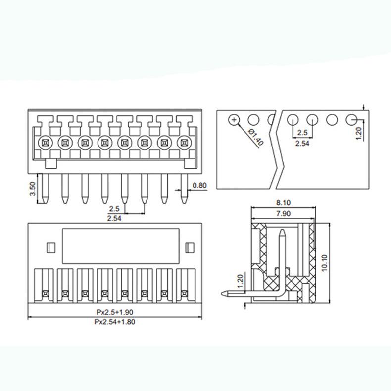
5.Dimensions
Angle
The most common bend is a 90° right-angle bend, which is also the default form of the "bending needle".
There are designs from other angles as well, but 90° is the industry standard and the most commonly used option.
Material and plating
Base material: Typically consistent with the terminal body, it is made of copper alloys such as brass and phosphor bronze, which are highly conductive, to ensure good current-carrying capacity and elasticity.
Electroplating: The curved needle part usually has the same electroplating layer as the needle foot, with tin plating being the most common. Tin plating provides good solderability, prevents oxidation of the copper substrate, and has a certain degree of corrosion resistance. In some more demanding applications, gold plating may be used to achieve excellent corrosion resistance and stable contact resistance.
forming process
The curved needle is molded in one step through a precise stamping and bending process. This requires the metal material to have good ductility to avoid cracks or stress concentration at the bend.
After the high-quality bent pin is formed, the bend should be smooth and burr-free, with precise angles, to ensure alignment when inserted into the socket and coplanarity during soldering.
Type of soldering leg
Through-hole type: The end of the bent pin is designed to pass through a through-hole on the PCB and then be fixed through wave soldering or manual soldering. This is the most secure connection method.
SMT (Surface Mount Technology) patch type: Although less common, there are also bent pins designed for surface mounting, with their solder pads located at the bottom of the bent portion, connected to the PCB through reflow soldering. This design requires higher strength for the terminal itself and higher requirements for the soldering process.
6.Advantages
☑ Adapt to multi-type sockets, device design is highly flexible
☑ Keying requirements can be met
☑ Universal installation method, suitable for various situations
summary
The curved pin section of the 2.5mm pitch plug-in terminal block is an ingenious and practical engineering design. Through a simple 90-degree bend, it cleverly addresses three core issues: internal space layout of electronic devices, wiring convenience, and connection reliability. When selecting, in addition to paying attention to electrical parameters such as current and voltage, one should also consider the molding quality of the curved pin, the plating process, and its compatibility with PCB pads. These are all crucial details that ensure the stability of the final product.
7.Application Of Pluggable Terminal Block
1.Motion controller 2.Three-phase power meter 3.Microcomputer protection device 4.Electric equipment
5.Automation equipment 6.Security equipment 7.Internet of things equipment
2.5mm pitch bent pin plug-in terminal blocks are widely used in various electronic devices with limited space, such as:
Industrial control: PLC, frequency converter, servo driver.
Communication equipment: routers, switches, base station modules.
Power system: electricity meter, protective relay.
Instruments and meters: data collectors, testing and measuring equipment.
8.Package Of Pluggable Terminal Block
We choose the high quality and safe packaging material to make sure your order won't be damaged during delivery.
These trade terms are acceptable:EXW,FOB,CFR,CIF.

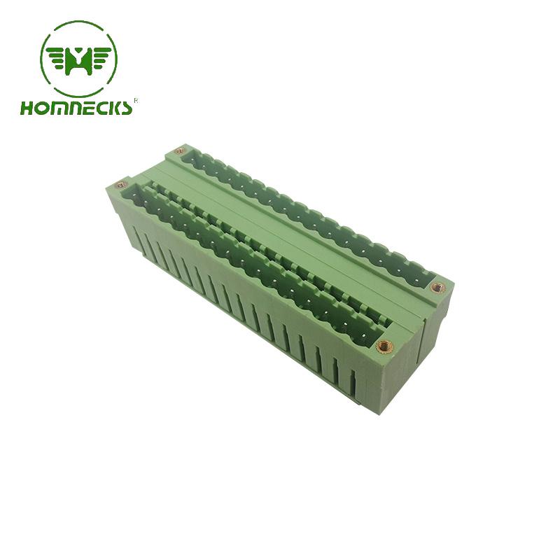
Brand:HOMNECKS Crafted with utmost precision and adhering to the highest industry standards, our 5.08mm Pitch Dual Row Straight Needle Terminal boasts exceptional reliability and durability. This makes it a perfect choice for your diverse range of electronic applications.
Details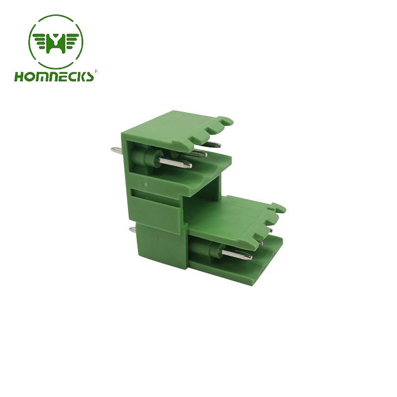
Brand:HOMNECKS 5.08 Dual Row Pluggable Straight Needle Terminal revolutionizes the way you operate in the world of electrical engineering.
Details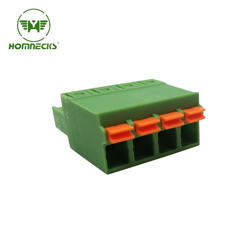
Brand:HOMNECKS Head for Pluggable Terminal Block , 5.08 Pitch,Screwless Numble Of Pole: we can make from 2P to 24P
Details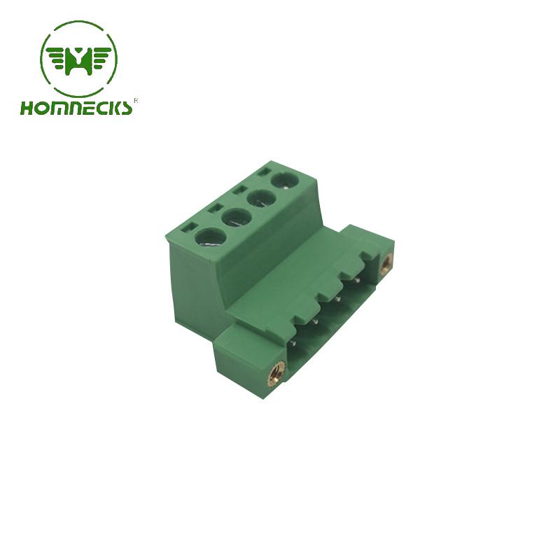
Brand:HOMNECKS 5.08 Pitch Pluggable Terminal Block Numble Of Pole: we can make from 2P to 24P
Details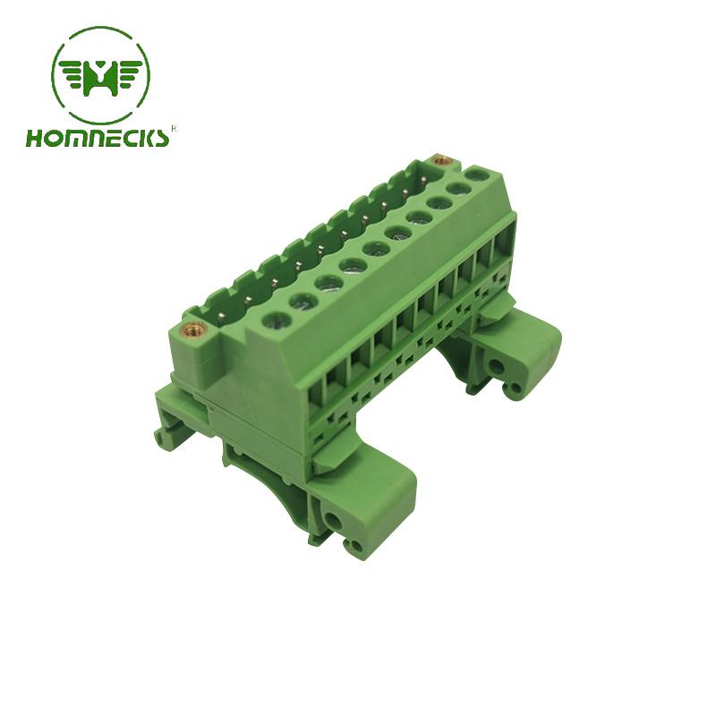
Brand:HOMNECKS Rail Plug-in type terminal block H2EUDBM-5.08
Details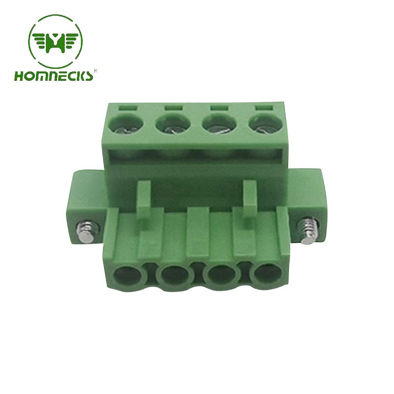
Brand:HOMNECKS Crafted with utmost precision, the housing is constructed from flame-retardant PA66 material, guaranteeing superior fire resistance. Complementing this, the metal components are expertly manufactured using copper plated with nickel, endowing the terminal with exceptional electrical conductivity.
Details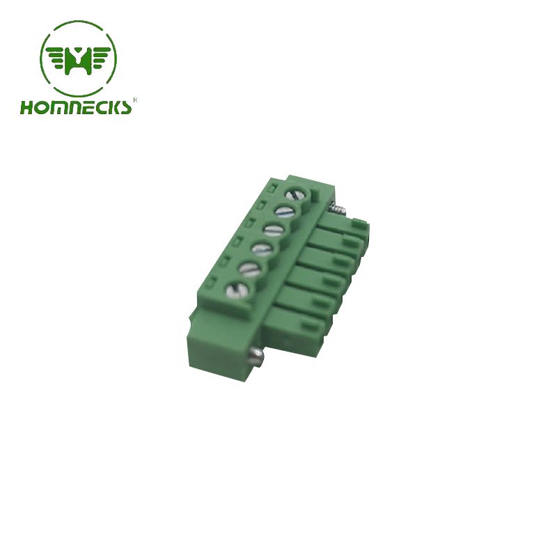
Brand:HOMNECKS Embrace professionalism and technical prowess with this phenomenal 3.81mm pitch PCB terminal. Take advantage of its remarkable features and unleash the full potential of your electronic endeavors. Experience excellence. Experience reliability. Experience progress.
Details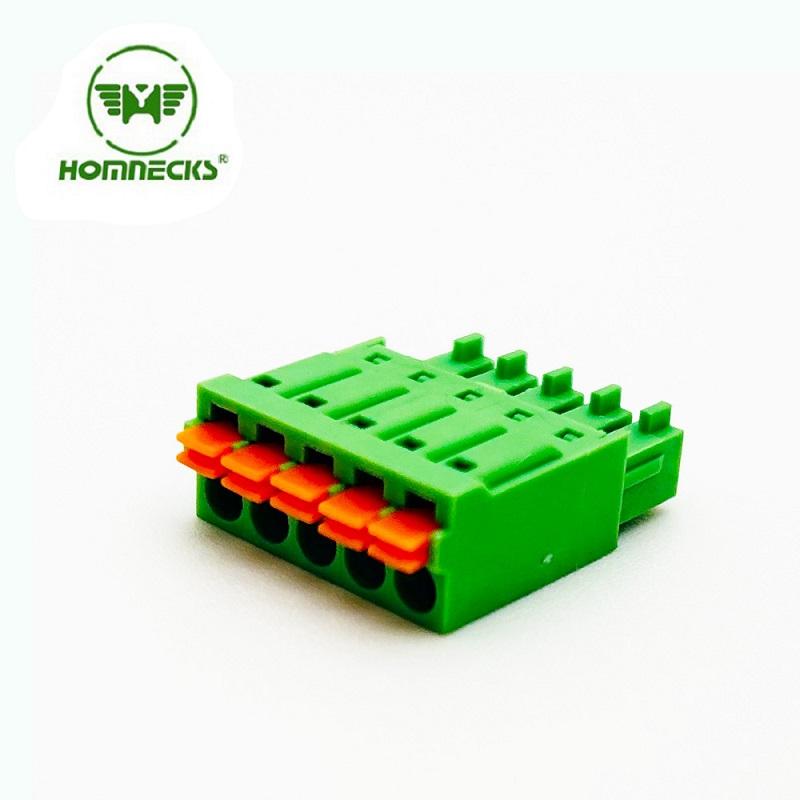
Brand:HOMNECKS 3.5mm pitch screw-less terminal connectors! Designed to optimize efficiency in your electrical projects
Details Contact Us
Signup our newsletter to get update information, promotion and insight.



 IPv6 network supported