English
 English
 Deutsch
 Español
 عربي
عربي हिंदी
हिंदी

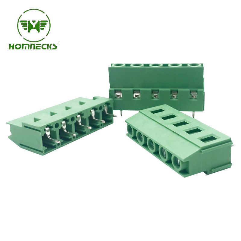
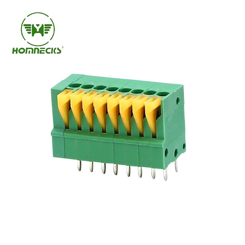
This 3.81mm Electrical Connector Block is designed for circuit boards and electrical connections, featuring a standard 3.81mm pitch for wide compatibility. It utilizes high-quality insulation and highly conductive metal contacts to ensure a stable, secure connection and high durability, making it suitable for a variety of applications, including industrial controls, power modules, and LED lighting.
Item No :
H15EDGAM-3.81Payment :
T/TProduct Origin :
ChinaColor :
green ,we can also make other color if meet moqThe H15EDGWC-3.81 Electrical Connector Block is a high-performance terminal block designed for printed circuit boards (PCBs) and electrical connections. It features a standard 3.81mm pitch, easily adapting to a variety of board layouts and making it ideal for applications such as industrial automation equipment, power modules, control systems, and lighting products.
Type: Pcb Pluggable Screw Terminal Block
Pole:
| 2 pin terminal block | 3 pin terminal block | 4 pin terminal block | 5 pin terminal block | 6 pin terminal block | 7 pin terminal block |
| 8 pin terminal block | 9 pin terminal block | 10 pin terminal block | 11 pin terminal block | 12 pin terminal block | 13 pin terminal block |
| 14 pin terminal block | 15 pin terminal block | 16 pin terminal block | 17 pin terminal block | 18 pin terminal block | 19 pin terminal block |
| 20 pin terminal block | 21 pin terminal block | 22 pin terminal block | 23 pin terminal block | 24 pin terminal block |

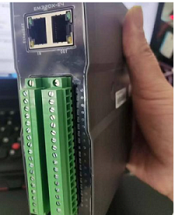
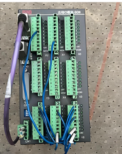
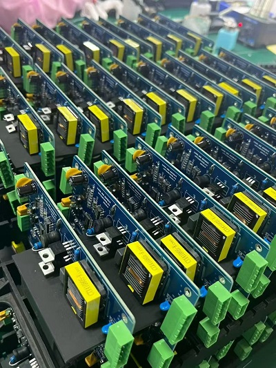
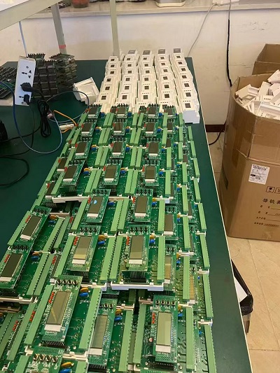
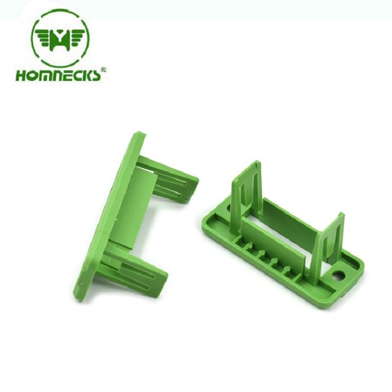
A: It passes signals and low‑power circuits straight through cabinet enclosure walls.
You skip messy through‑cable stripping, extra splices and heat‑shrink joints.
During panel assembly and field service, you can separate cabinet‑internal wiring from external field wiring.
If you need to pull the cabinet door or remove internal modules, you simply unplug instead of reworking every wire.
Most OEMs use it for PLC I/O, sensor lines and small‑actuator control loops。
A: Stick to 0.5‑2.5 mm² solid or stranded wire (AWG 24‑14).
Standard rating sits around 300 V / 15 A under IEC and UL conditions.
Do not run full‑power motor circuits through these blocks.
Field experience shows overheating almost always comes from oversized cables or poorly‑torqued screws, not product defects.
A: Target 0.5‑0.6 Nm for common M3 screw versions.
Two real‑world mistakes happen often.
Too‑low torque creates loose connections that heat‑up under vibration.
Over‑torque cracks plastic housing or strips internal brass threads.
Use a torque‑controlled screwdriver on production lines.
For site work, tighten firm and add a small extra turn — do not force it hard.
A: 5.08 mm is a standard pitch, but mechanical and plating differences exist across vendors.
Pin spacing fits physically, yet housing latch dimensions, contact spring pressure and pin thickness may differ.
Mix‑and‑match can cause intermittent contact after vibration or temperature cycling.
Best practice: use matched pairs from one supplier for every cabinet project.
If you must cross‑mate, run vibration and thermal cycle validation before series production.
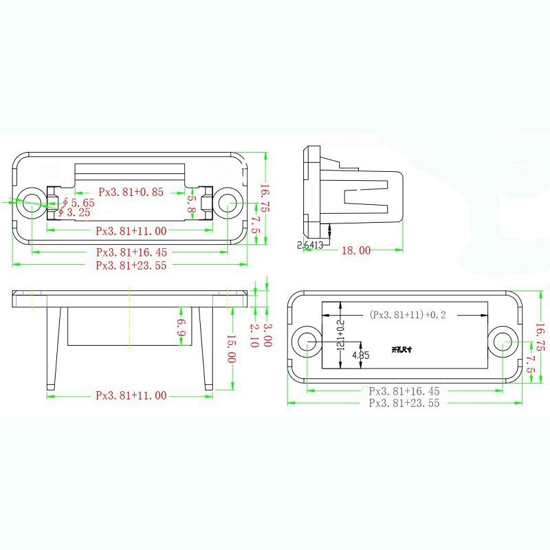
A: Follow supplier cut‑out drawing exactly. Too‑large cut‑outs weaken flange fixing and break IP sealing.
Deburr sharp metal edges on cabinet holes. Sharp burrs will scratch terminal plastic during installation.
Leave clearance around adjacent components. You still need screwdriver access for screw terminals after mounting.
Check alignment before tightening flange screws. Misaligned mounting stresses the housing and causes hidden damage later in service.
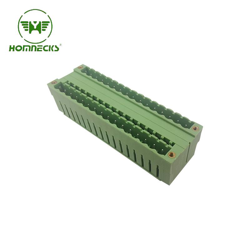
Brand:HOMNECKS Crafted with utmost precision and adhering to the highest industry standards, our 5.08mm Pitch Dual Row Straight Needle Terminal boasts exceptional reliability and durability. This makes it a perfect choice for your diverse range of electronic applications.
Details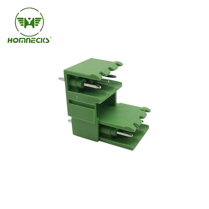
Brand:HOMNECKS 5.08 Dual Row Pluggable Straight Needle Terminal revolutionizes the way you operate in the world of electrical engineering.
Details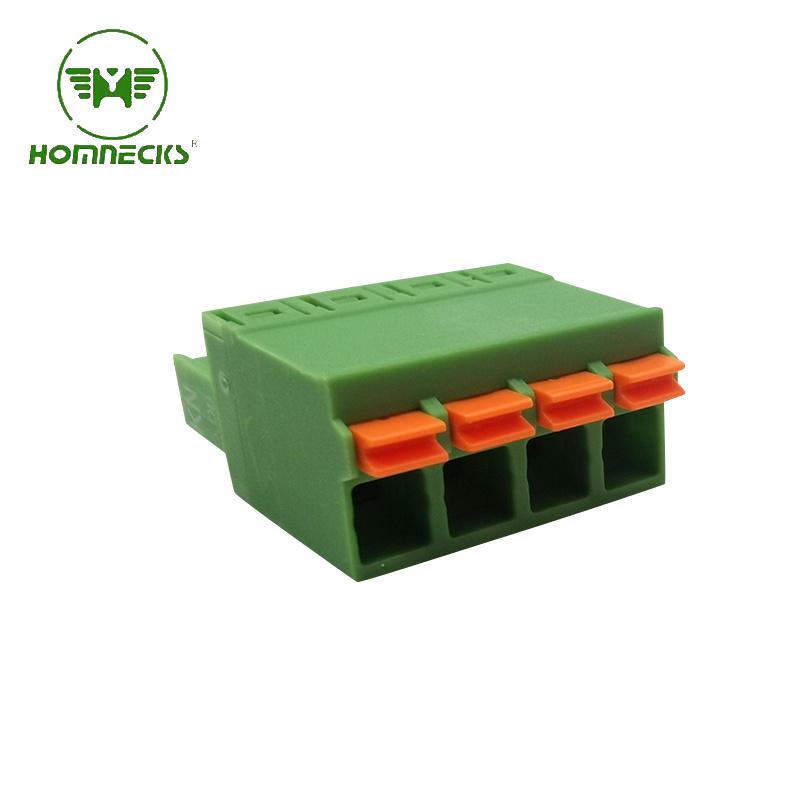
Brand:HOMNECKS Head for Pluggable Terminal Block , 5.08 Pitch,Screwless Numble Of Pole: we can make from 2P to 24P
Details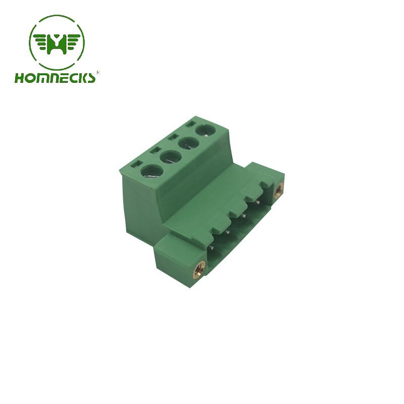
Brand:HOMNECKS 5.08 Pitch Pluggable Terminal Block Numble Of Pole: we can make from 2P to 24P
Details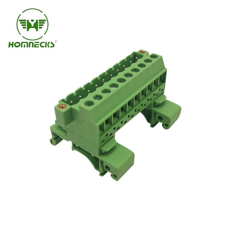
Brand:HOMNECKS Rail Plug-in type terminal block H2EUDBM-5.08
Details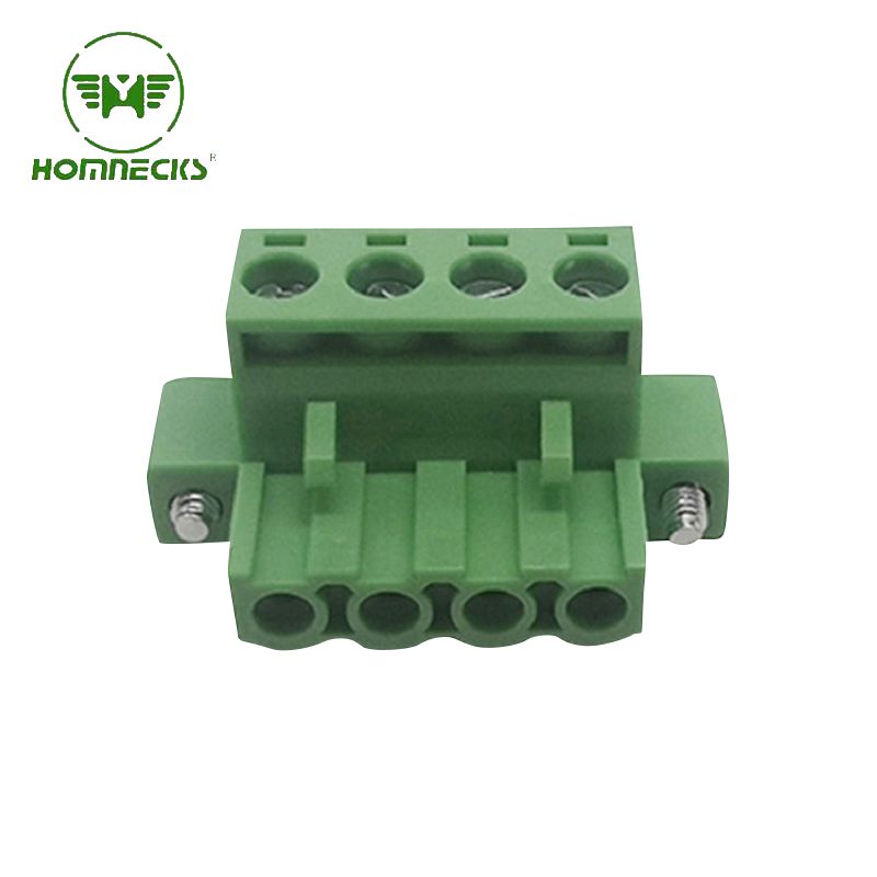
Brand:HOMNECKS Crafted with utmost precision, the housing is constructed from flame-retardant PA66 material, guaranteeing superior fire resistance. Complementing this, the metal components are expertly manufactured using copper plated with nickel, endowing the terminal with exceptional electrical conductivity.
Details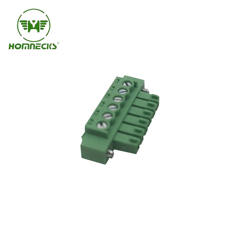
Brand:HOMNECKS Embrace professionalism and technical prowess with this phenomenal 3.81mm pitch PCB terminal. Take advantage of its remarkable features and unleash the full potential of your electronic endeavors. Experience excellence. Experience reliability. Experience progress.
Details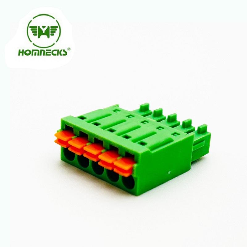
Brand:HOMNECKS 3.5mm pitch screw-less terminal connectors! Designed to optimize efficiency in your electrical projects
Details Contact Us
Signup our newsletter to get update information, promotion and insight.



 IPv6 network supported