English
 English
 Deutsch
 Español
 عربي
عربي हिंदी
हिंदी

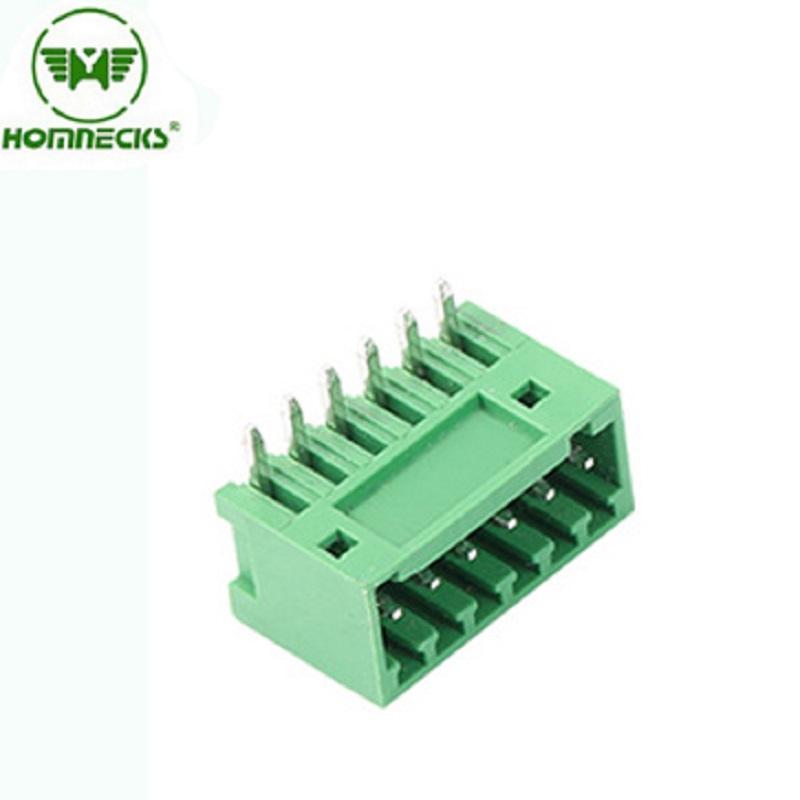
Brand:HOMNECKS
The bent pin, also known as the "L-shaped pin" or "90-degree pin", refers to a structure where the pin extends from the bottom of the terminal insulation body and is immediately bent at an approximate 90-degree angle, forming an "L" shape.
Item No :
H2EDGCR-2.54Payment :
T/TProduct Origin :
ChinaColor :
green ,we can also make other color if meet moq2.54 terminal blocks Right Pin header
Design structure and material
Configuration: Transition from a vertical segment to a horizontal segment. The vertical segment is used for securing to the terminal body, while the horizontal segment is used for soldering to the PCB board.
Material: Similar to straight needles, typically:
Brass: economical, with good mechanical strength and conductivity.
Electroplating: Surface treatment is also carried out, with tin plating being the most common. For high-demand applications, gold plating or selective gold plating may be used.
Molding process: One-time molding through precise stamping and bending molds. High-quality bending needles require smooth bends, free of burrs and cracks, to ensure mechanical strength.
1.Type and Pole
The core purpose and advantages of the curved needle design
Saving vertical space: This is the fundamental purpose. After the bent pin terminal is soldered, its main body is parallel to the PCB board, rather than perpendicular. This greatly reduces the height of the entire module in the vertical direction of the PCB board, making it ideal for thin devices with limited housing height.
Implement horizontal wiring: The wires are horizontally connected from the side of the terminal, and the wire harness can be routed closely along the PCB board, making the internal structure of the device very compact and tidy, facilitating cable management.
Panel installation compatibility: This is an extremely important application of the bent pin. The terminal strip can be installed closely to the inside of the equipment panel, with the bent pin passing through a pre-opened hole in the panel and soldered to the main PCB board inside. This way, users can connect wires from the outside of the equipment, while all complex circuitry is hidden behind the panel.
Provide a certain degree of strain relief: The "L" shape structure itself is more capable of withstanding lateral tensile and torsional forces from the wire than a straight pin, as it can distribute the stress to the solder joints and PCB board rather than directly acting on the vertical pins.
Type: Pcb Pluggable Screw Terminal Block
Pole:
| 2 pin terminal block | 3 pin terminal block | 4 pin terminal block | 5 pin terminal block | 6 pin terminal block | 7 pin terminal block |
| 8 pin terminal block | 9 pin terminal block | 10 pin terminal block | 11 pin terminal block | 12 pin terminal block | 13 pin terminal block |
| 14 pin terminal block | 15 pin terminal block | 16 pin terminal block | 17 pin terminal block | 18 pin terminal block | 19 pin terminal block |
| 20 pin terminal block | 21 pin terminal block | 22 pin terminal block | 23 pin terminal block | 24 pin terminal block |
2.Material Of Pluggable Terminal Block
| Housing | PA66, UL94V-0 |
| Pin header | Copper alloy ,Tin Plated |
The part soldered on the PCB board: Process and solder joint analysis
The welding part of the curved needle is its horizontal segment, which determines that its welding process and weld joint morphology are significantly different from those of the straight needle.
1. Coordination between pins and pads
PCB pad: The design on the PCB is for surface-mount pads, not through-holes. The pads are located directly below the horizontal segment of the pins.
Cooperation method: The horizontal segment of the lead is directly attached to the solder pad on the PCB. Sometimes, there is a small bend or groove at the end of the lead, which is used for temporary positioning through the viscosity of the solder paste before soldering.
2. Welding process
The bent pin terminal mainly adopts the reflow soldering process.
Solder paste printing: First, accurately print solder paste onto the solder pad positions on the PCB through a steel mesh.
Mounting: Using automated equipment (pick-and-place machine) or manual labor, accurately place the bent terminals onto the PCB, ensuring that the horizontal segment of the pin makes good contact with the solder paste pad.
Reflow soldering: The entire PCB passes through a reflow oven. The high temperature inside the oven melts the solder paste, and the liquid solder, due to surface tension, naturally "climbs" and encapsulates the horizontal segment of the lead, forming a full solder joint.
Cooling: The solder cools and solidifies, forming a firm electrical and mechanical connection.
Wave soldering can also be used, but it requires specialized fixtures to protect the plastic body of the terminals from the impact of high-temperature solder, and it is not as convenient and reliable as reflow soldering.
3. Solder joint morphology and requirements
A high-quality bent-pin solder joint should possess:
Solder filling is full: The solder should fully wet the pins and pads, and form a good meniscus on the side of the pins.
Pin coplanarity: The horizontal segments of all pins must be parallel to the PCB surface and have consistent heights, otherwise it will lead to poor soldering or open circuits. This is a key quality indicator in the manufacturing of bent pin terminals.
Accurate positioning: The terminals must not be displaced before soldering to ensure that all pins are accurately aligned on their respective solder pads.
3.Electrical Of Pluggable Terminal Block
| Rated Voltage |
UL IEC 150V 130V |
| Rated Current | 5A 10A |
| Contact Resistance | 20mΩ(MAX) |
| Insulation Resistance | 500MΩ/DC500V |
| Withstanding Voltage | AC 1250V/1 Min |
4.Mechanical Of Pluggable Terminal Block
| Temp. Range | -40℃~ +105℃ |
| MAX Soldering | +250, for 5 Sec. |
5.Dimensions
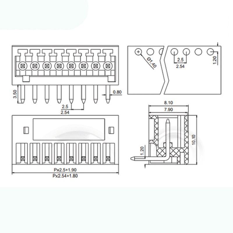
6.Advantages
☑ Adapt to multi-type sockets, device design is highly flexible
☑ Keying requirements can be met
☑ Universal installation method, suitable for various situations
7.Application Of Pluggable Terminal Block
1.Motion controller 2.Three-phase power meter 3.Microcomputer protection device 4.Electric equipment
5.Automation equipment 6.Security equipment 7.Internet of things equipment
8.Package Of Pluggable Terminal Block
We choose the high quality and safe packaging material to make sure your order won't be damaged during delivery.
These trade terms are acceptable:EXW,FOB,CFR,CIF.

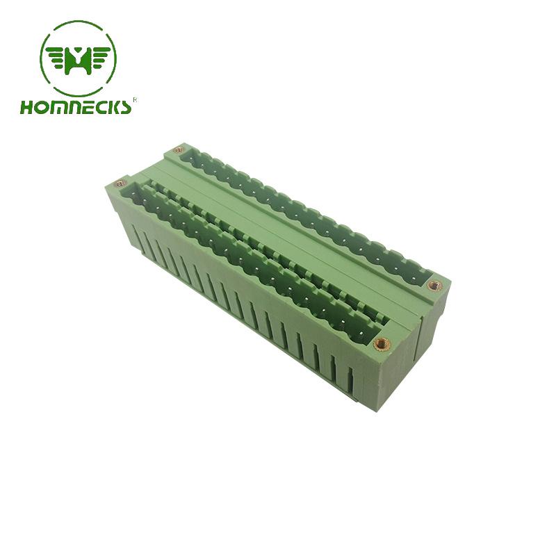
Brand:HOMNECKS Crafted with utmost precision and adhering to the highest industry standards, our 5.08mm Pitch Dual Row Straight Needle Terminal boasts exceptional reliability and durability. This makes it a perfect choice for your diverse range of electronic applications.
Details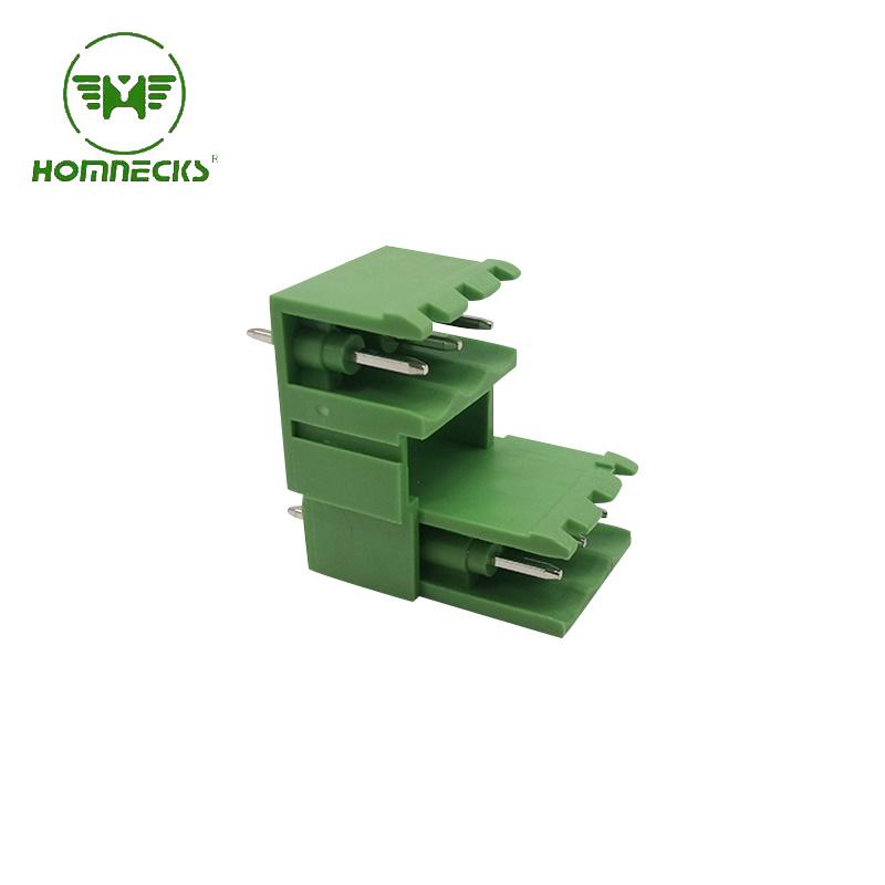
Brand:HOMNECKS 5.08 Dual Row Pluggable Straight Needle Terminal revolutionizes the way you operate in the world of electrical engineering.
Details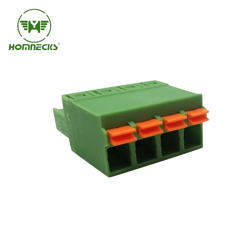
Brand:HOMNECKS Head for Pluggable Terminal Block , 5.08 Pitch,Screwless Numble Of Pole: we can make from 2P to 24P
Details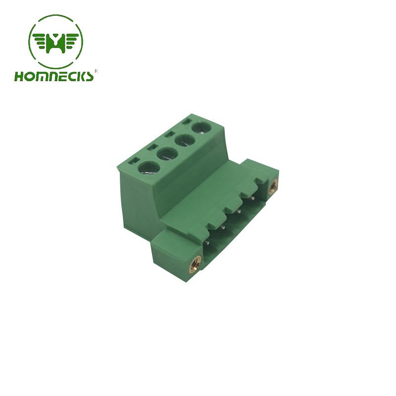
Brand:HOMNECKS 5.08 Pitch Pluggable Terminal Block Numble Of Pole: we can make from 2P to 24P
Details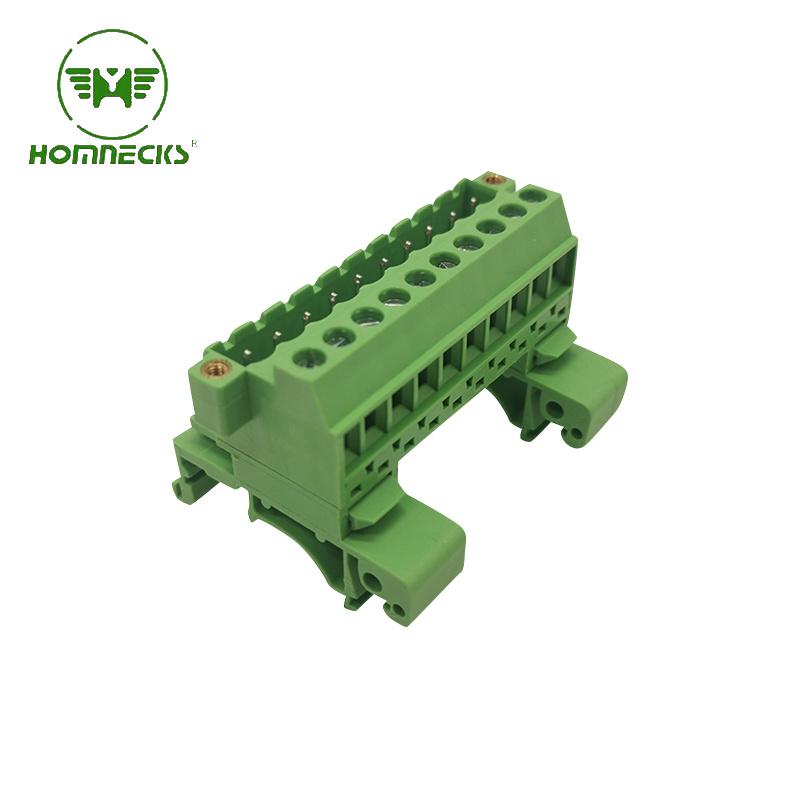
Brand:HOMNECKS Rail Plug-in type terminal block H2EUDBM-5.08
Details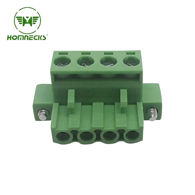
Brand:HOMNECKS Crafted with utmost precision, the housing is constructed from flame-retardant PA66 material, guaranteeing superior fire resistance. Complementing this, the metal components are expertly manufactured using copper plated with nickel, endowing the terminal with exceptional electrical conductivity.
Details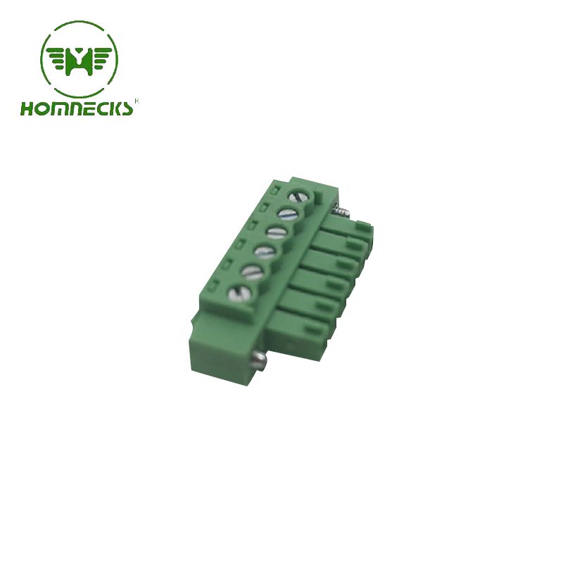
Brand:HOMNECKS Embrace professionalism and technical prowess with this phenomenal 3.81mm pitch PCB terminal. Take advantage of its remarkable features and unleash the full potential of your electronic endeavors. Experience excellence. Experience reliability. Experience progress.
Details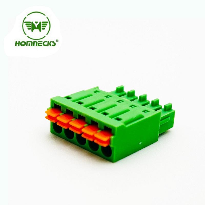
Brand:HOMNECKS 3.5mm pitch screw-less terminal connectors! Designed to optimize efficiency in your electrical projects
Details Contact Us
Signup our newsletter to get update information, promotion and insight.



 IPv6 network supported