English
 English
 Deutsch
 Español
 عربي
عربي हिंदी
हिंदी

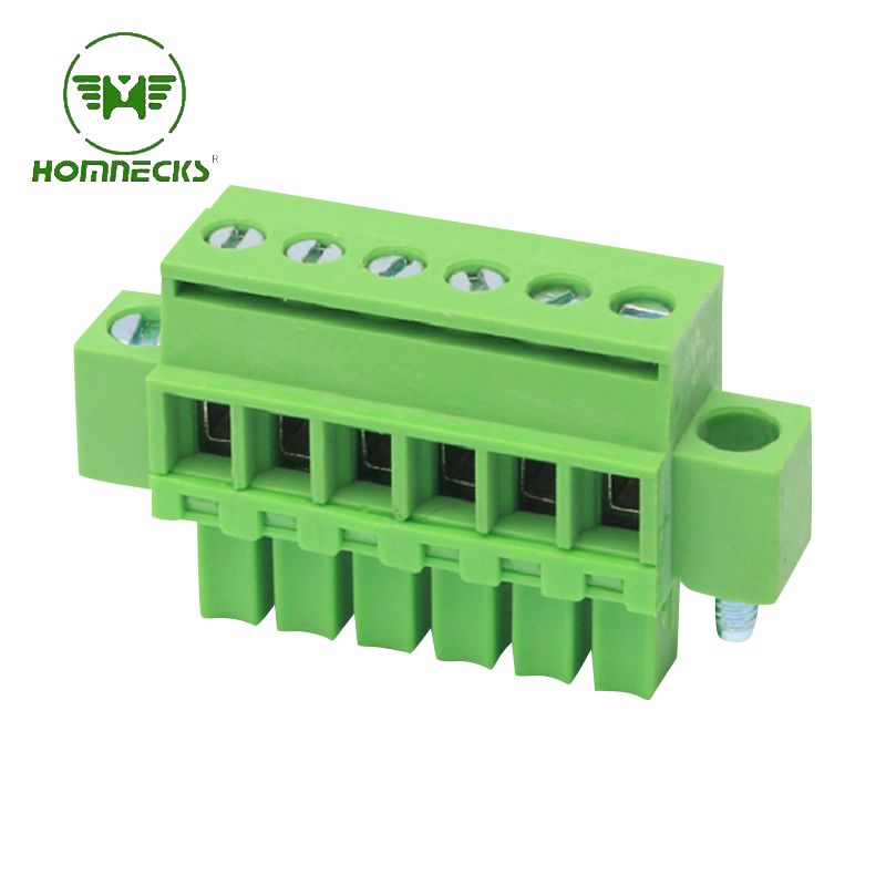
The terminal is suitable for a variety of wire diameters, supports single-strand and multi-strand wires, and is easy to install and maintain. It is widely used in industrial control, lighting equipment, power systems, communication equipment and household appliances.
Item No :
H15EDGKN-3.5Payment :
T/TProduct Origin :
ChinaColor :
green ,we can also make other color if meet moqThis 3.81mm pitch PCB mounting screw terminal connector has a compact design and is suitable for wiring needs of various electronic circuit boards. It is made of high-quality materials to ensure excellent electrical performance and mechanical stability. The terminal fixes the wire with screws, which is firmly connected and can effectively prevent loosening and poor contact. It is especially suitable for use in vibration environments.
The terminal spacing is 3.81 mm, which is suitable for a more compact wiring design and effectively saves circuit board space. Its pins are made of tin-plated copper alloy, which has good conductivity and corrosion resistance, ensuring long-term stable operation. The shell is made of flame-retardant plastic, which is resistant to high temperature and impact, and meets the safety requirements in industrial applications.
Type: Pcb Pluggable Screw Terminal Block
Pole:
| 2 pin terminal block | 3 pin terminal block | 4 pin terminal block | 5 pin terminal block | 6 pin terminal block | 7 pin terminal block |
| 8 pin terminal block | 9 pin terminal block | 10 pin terminal block | 11 pin terminal block | 12 pin terminal block | 13 pin terminal block |
| 14 pin terminal block | 15 pin terminal block | 16 pin terminal block | 17 pin terminal block | 18 pin terminal block | 19 pin terminal block |
| 20 pin terminal block | 21 pin terminal block | 22 pin terminal block | 23 pin terminal block | 24 pin terminal block |
| Housing | PA66, UL94V-0 |
| Screw | M2.0 steel,Zinc plated,“-” slot type |
| Contact | Copper alloy,Tin plated |
| Clamp | Copper alloy ,Tin Plated |
| Rated Voltage |
UL IEC 300V 250V |
| Rated Current | 8A 7A |
| Contact Resistance | 20mΩ(MAX) |
| Insulation Resistance | 500MΩ/DC500V |
| Withstanding Voltage | AC 1500V/1 Min |
| Wire range | 28-16 awg |
| Temp. Range | -40℃~ +105℃ |
| MAX Soldering | +250, for 5 Sec. |
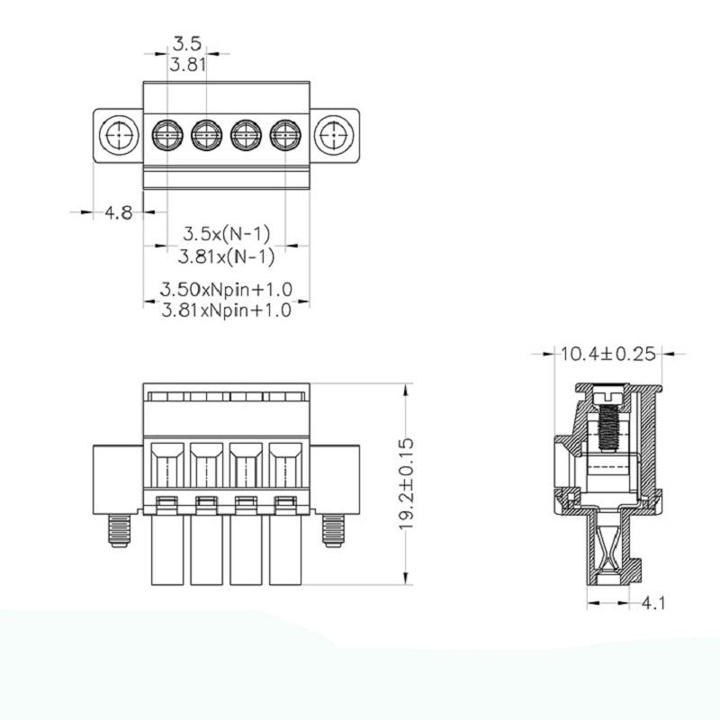
☑ Adapt to multi-type sockets, device design is highly flexible
☑ Keying requirements can be met
☑ Universal installation method, suitable for various situations
We choose the high quality and safe packaging material to make sure your order won't be damaged during delivery.
These trade terms are acceptable:EXW,FOB,CFR,CIF.

1.Motion controller 2.Three-phase power meter 3.Microcomputer protection device 4.Electric equipment
5.Automation equipment 6.Security equipment 7.Internet of things equipment
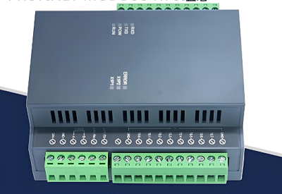
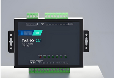
A: This is a straight‑through plug with side mounting flanges.
Flanges lock the plug to chassis or metal brackets with screws.
Cable pull stress transfers to the flange, not solder connections.
180‑degree straight layout works well for vertical wiring inside enclosures.
It is commonly used for PLC I/O, sensor and small actuator signal circuits.
Whole wiring harnesses can be unplugged for fast maintenance.
It is built for low‑voltage signal loops, not high‑power motor loads.
A: Typical ratings: 300 V, 8‑10 A per contact under IEC and UL standards.
Compatible with 0.5‑1.5 mm² solid or stranded conductors.
Fine‑stranded wires require wire ferrules for reliable contact.
Do not connect heavy motor power circuits to this connector.
On‑site feedback shows most connection faults come from improper wire preparation, not component defects.
A: Many installers over‑tighten flange fixing screws.
Too much torque may crack the plastic housing or deform mounting brackets.
Ensure flange surfaces sit flat against mounting faces.
Deburr metal mounting holes. Sharp burrs create hidden mechanical stress.
Never force‑push the plug into the header. Excessive force bends pins or damages locking structures.
Check full seating after mating. You should feel a clear locking click.
Avoid pulling cables directly on the plug body to prevent solder joint damage.
A: 3.81 mm pitch is industry‑standard, so parts may fit physically.
But pin thickness, contact depth, flange dimensions and spring pressure vary across brands.
Cross‑brand mating may cause intermittent contact after cabinet vibration and temperature swings.
Use matched plug‑header sets from one supplier for mass‑produced cabinets.
If cross‑brand pairing cannot be avoided, run vibration and thermal‑cycle tests before large‑volume production.
A: Inspect pin straightness on incoming batches. Bent pins cause partial mating and unstable signals.
Check flange mounting holes for deformation.
Test plug engagement and release for smooth operation without jamming.
During cabinet commissioning, perform light pull tests on each wired cable.
Confirm flange absorbs cable tension instead of solder joints.
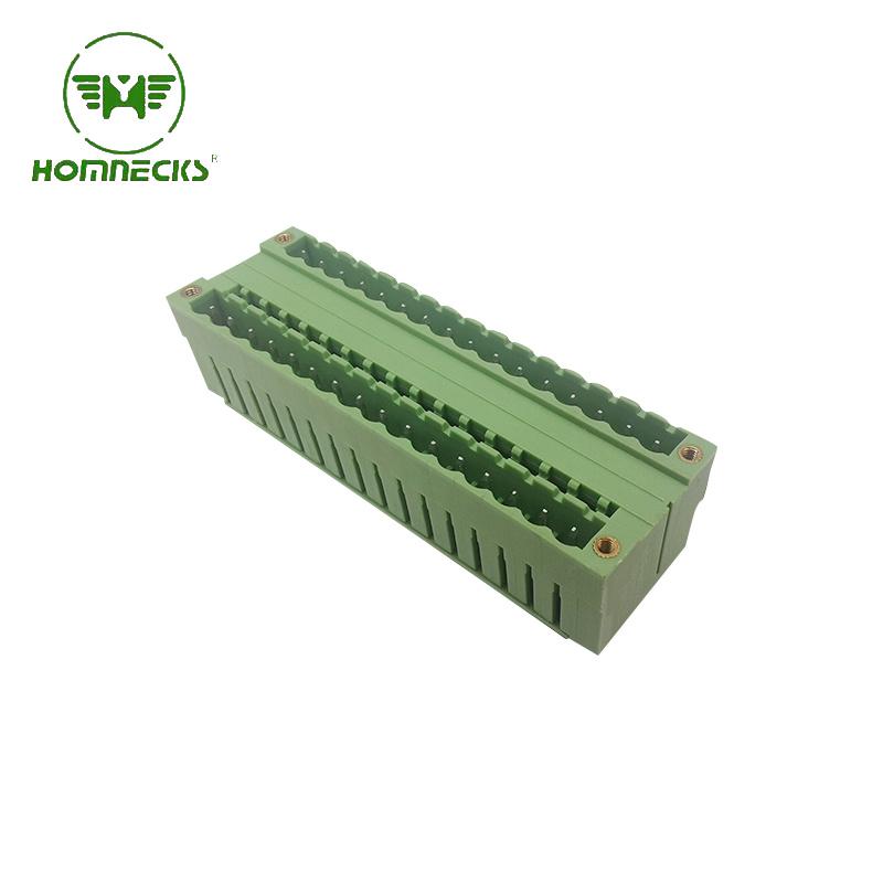
Brand:HOMNECKS Crafted with utmost precision and adhering to the highest industry standards, our 5.08mm Pitch Dual Row Straight Needle Terminal boasts exceptional reliability and durability. This makes it a perfect choice for your diverse range of electronic applications.
Details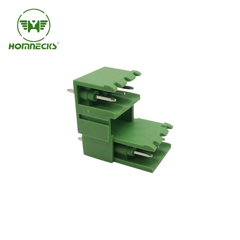
Brand:HOMNECKS 5.08 Dual Row Pluggable Straight Needle Terminal revolutionizes the way you operate in the world of electrical engineering.
Details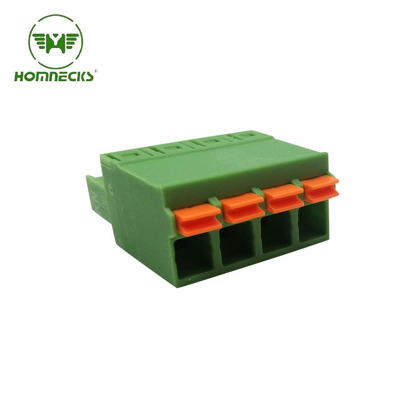
Brand:HOMNECKS Head for Pluggable Terminal Block , 5.08 Pitch,Screwless Numble Of Pole: we can make from 2P to 24P
Details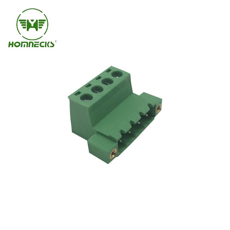
Brand:HOMNECKS 5.08 Pitch Pluggable Terminal Block Numble Of Pole: we can make from 2P to 24P
Details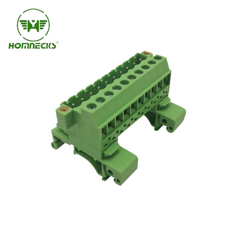
Brand:HOMNECKS Rail Plug-in type terminal block H2EUDBM-5.08
Details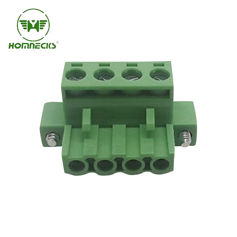
Brand:HOMNECKS Crafted with utmost precision, the housing is constructed from flame-retardant PA66 material, guaranteeing superior fire resistance. Complementing this, the metal components are expertly manufactured using copper plated with nickel, endowing the terminal with exceptional electrical conductivity.
Details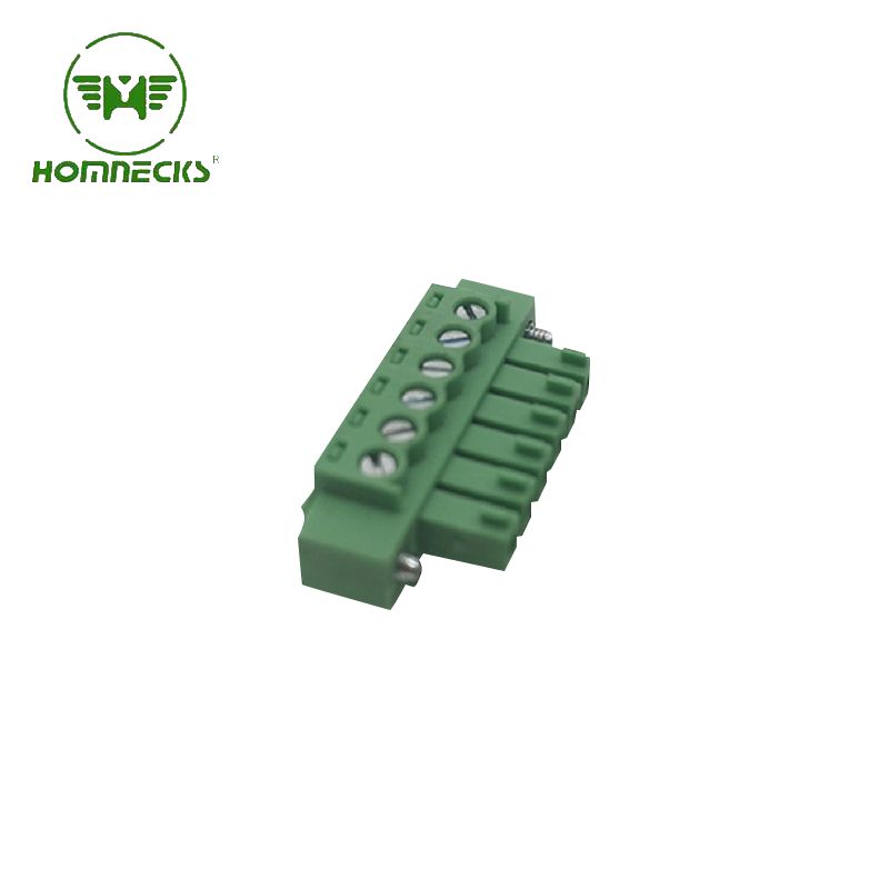
Brand:HOMNECKS Embrace professionalism and technical prowess with this phenomenal 3.81mm pitch PCB terminal. Take advantage of its remarkable features and unleash the full potential of your electronic endeavors. Experience excellence. Experience reliability. Experience progress.
Details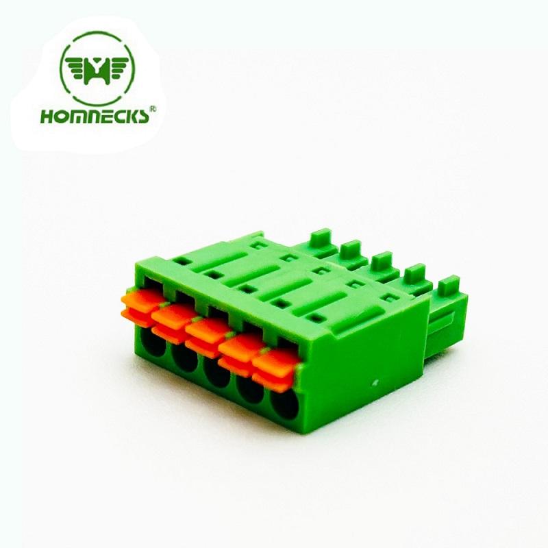
Brand:HOMNECKS 3.5mm pitch screw-less terminal connectors! Designed to optimize efficiency in your electrical projects
Details Contact Us
Signup our newsletter to get update information, promotion and insight.



 IPv6 network supported